Vacuum overload fuse

A fuse and vacuum technology, which is applied in the field of vacuum overload fuses, can solve the problems of large volume, insensitivity, and complex structure of combined electrical appliances, and achieve the effects of sensitive action, no explosion hazard, and small volume

Inactive Publication Date: 2007-01-24
山东晨鸿电气有限公司
View PDF0 Cites 0 Cited by
  • Summary
  • Abstract
  • Description
  • Claims
  • Application Information

AI Technical Summary

Problems solved by technology

Due to the vertical arrangement of the fuses, the entire combined electrical appliance is bulky and complex in structure
In large and medium-sized equipment, load switches are usually used in combination with existing current-limiting fuses. It is more reliable to use current-limiting fuses for short-circuit protection. However, using load switches for overload protection is generally done through relays. At the same time It takes a certain amount of time to act, is not sensitive enough, and has poor reliability

Method used


Image

  • Vacuum overload fuse
  • Vacuum overload fuse
  • Vacuum overload fuse

Examples


Embodiment Construction

[0015] The present invention will be further described below in conjunction with the accompanying drawings of the embodiments.

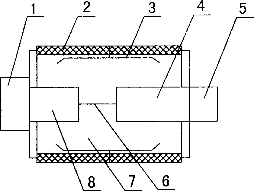
[0016] Such as figure 1 As shown, the vacuum overload fuse of the present invention is a small-sized product, and the melt (copper-nickel alloy wire) 6 is sealed in the vacuum chamber 7 of the insulating porcelain sleeve 2, and the vacuum degree of the vacuum chamber 7 is 5×10 -4 Pa, a metal shield 3 is set between the melt 6 and the insulating porcelain sleeve 2, and the two ends of the melt 6 are connected to the external terminals 1 and 5 through conductive rods (oxygen-free copper rods) 8 and 4 . Terminals 1 and 5 can be processed into any shape suitable for installation as required.

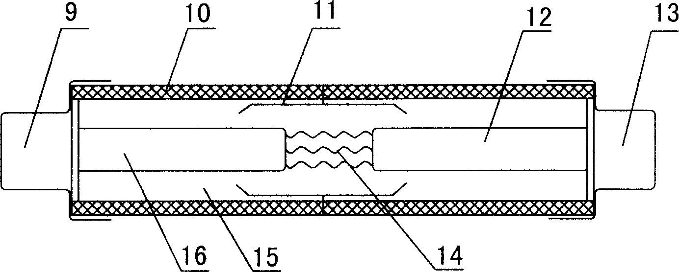
[0017] Such as figure 2 As shown, the vacuum overload fuse of the present invention is a medium-sized and large-sized product with a long length, and the melt (copper-nickel alloy strip) 14 is sealed in the vacuum chamber 15 of the insulating porcelain sleeve 10...


PUM


Abstract

This invention relates to a vacuum overload fuse including a connecting end and a fuse mass, which is sealed in the vacuum cavity of an insulation porcelain bushing and both ends of which are connected with connection ends of outside by conduction rods and a metal shield cover is set between the fuse mass and the insulation porcelain bushing. This invented fuse combines the technologies of fuse and vacuum, in which, when a current reaches to a set fuse current, the fuse mass is fused for protection.

Description

technical field [0001] The invention relates to a vacuum overload fuse used for protecting electric equipment. Background technique [0002] Fuses are generally installed vertically above or below the load switch. It is horizontally arranged directly above the vacuum interrupter, and the end of the fuse with the striker faces the tripping mechanism triggered by the striker. When a fault current occurs in the line, such as a short circuit, the tripping mechanism is triggered by the striker inside the fuse, which drives the operating mechanism to disconnect the vacuum interrupter. Due to the vertical arrangement of the fuses, the entire combined electrical appliance is bulky and complex in structure. In large and medium-sized equipment, load switches are usually used in combination with existing current-limiting fuses. It is more reliable to use current-limiting fuses for short-circuit protection, but using load switches for overload protection is generally done through rela...

Claims


Application Information

Patent Timeline
Patent Type & Authority Applications(China)
IPC IPC(8): H01H73/34
Inventor 张文波刘永飞冉隆科
Owner 山东晨鸿电气有限公司
Why Eureka
Try Eureka