Screw pile, thread pile piling equipment and piling method

A technology of threaded piles and screw piles, applied in sheet pile walls, foundation structure engineering, construction, etc., can solve the problems of insufficient self-weight of equipment, failure to achieve occlusal, insufficient pressure, etc., achieve power output, save electricity and time, and expand applications The effect of increasing the range and drilling depth

Inactive Publication Date: 2007-01-31
卓典设计(海南)有限公司
View PDF5 Cites 35 Cited by
  • Summary
  • Abstract
  • Description
  • Claims
  • Application Information

AI Technical Summary

Problems solved by technology

②The above equipment often occurs in engineering practice because when the bearing capacity of the soil is large, the self-weight or pressure of the equipment is not enough, and the reaction force of the soil on the drilling tool is greater than the pressure of the drilling rig, resulting in the "slipping" phenomenon of the drill pipe rotating in situ. Once slipping, the drill bit will rotate on the spot, and the thread will be lost, failing to meet the basic technical requirements for the undisturbed soil and piles to occlude
⑤ The concrete piles formed by pump pressure are not stirred, and the homogeneity of the concrete is also affected. At present, the piles formed by cast-in-place have no solution to such disadvantages
In fact, the root cause of the low bearing capacity of cast-in-place full-threaded piles is that they are limited by the strength of their own materials, so that the stress transmission function of the pile threads has not been clearly exerted, and the pile head is often damaged before the soil body is damaged. , so that the bearing capacity of the pile cannot reach the expected effect

Method used


Image

  • Screw pile, thread pile piling equipment and piling method
  • Screw pile, thread pile piling equipment and piling method
  • Screw pile, thread pile piling equipment and piling method

Examples


Embodiment Construction

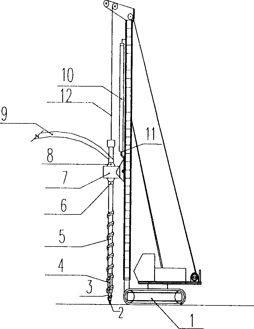
[0033] Structural drawings further describe the present invention.

[0034] Such as image 3 , Figure 4 As shown, the pile-forming equipment of screw pile and screw pile of the present invention mainly consists of the following components: a body, an oil cylinder, a motor, an automatic control device, and a delivery pipeline. The body mainly includes a frame 1, a power head 7 and a drill rod 6, The power head 7 is installed on the stand of the frame 1, the motor 16 is installed on the body base 1, the motor 16 is connected with the power head 7 through the telescopic oil cylinder 10, the fixture 8 on the drill pipe 6 is connected with the movable fixture 8 of the power head 7 Connected, the power head and the inner drill pipe 6-1 are connected with a reciprocating helical bayonet 14, the concrete delivery pipeline 9 is connected with the inner drill pipe 6-1, and the lower end of the telescopic oil cylinder 10 is provided with a feed speed sensor 11, and the oil cylinder Th...


PUM


Abstract

This invention relates to screw stake, making screw stake equipment and the making method. The making screw stake equipment is mainly composed of the engine body, the oil cylinder, the hydraulic electric engine, the automation equipment and the transfer piping. The power head is installed on the engine body base's stand support. The hydraulic electric engine is installed on the engine body's base. The hydraulic electric engine connects with the power head through the power head. The drill pipe's clamp apparatus connects with the power's removable clamp apparatus. The transfer piping connects with the inner drill pipe. The automation equipment separately connects with the hydraulic electric engine and the oil cylinder. This invention has the following advantages: the power output saves electricity and time, it enlarges the equipment's application range and the construction speed excels other similar inventions evidently; the equipment adopts the extensible drill pipe, the drill's drilling depth largely improves; the three independent drill heads' structure has the unique ability of thrice enlarging aperture; it realizes the revolution and the raising to keep synchronous and non- synchronous; it adopts low gravity center pile frame, the equipment's weight is reduced evidently, the safety improves; it realizes the stake's stirring and evidently improves the stake's uniformity

Description

technical field [0001] The invention relates to a pile-forming device and two pile-forming methods. Background technique [0002] Invention patent ZL03128265.2 semi-screw pile and its pile-forming method and ZL9996119602.5 a construction method of cast-in-situ piles. Both of the invented pile-forming methods involve the construction machinery that has been successfully developed: ZL03272306.7 has a thread guide The screw thread equipment of the device, CN1417420.A thread equipment with drilling lead synchronous tracking automatic control system and CN200310117711.9 half screw pile and its processing method and device. Among them, semi-screw piles are academically referred to as screw piles. [0003] The equipment developed according to the above construction methods, methods and processing methods is to solve the key technical requirements of thread / screw forming piles or holes. The technology that the rod rotates and lifts up and down synchronousl...

Claims


Application Information

Patent Timeline
Patent Type & Authority Applications(China)
IPC IPC(8): E02D5/34E02D5/56
Inventor 彭桂皎
Owner 卓典设计(海南)有限公司
Why Eureka
Try Eureka