Drilling device for road construction and using method thereof

A technology for drilling device and road construction, applied in drilling equipment and methods, support device, earthwork drilling and other directions, can solve the problems of complex shock absorption mechanism, increase drilling cost, drill bit shaking, etc., and reduce the workload of workers , Reduce the cost of punching and improve the effect of punching accuracy

Inactive Publication Date: 2020-08-11
萧县众科电磁检测有限公司
View PDF9 Cites 5 Cited by
  • Summary
  • Abstract
  • Description
  • Claims
  • Application Information

AI Technical Summary

Problems solved by technology

[0002] At present, steel bars and pillars need to be installed during the construction of traffic roads. At this time, holes need to be drilled on the road to lay a foundation for the construction. The existing drilling methods generally use the staff to hold the drilling machine to align the drill bit with the required drilling. Drilling the area increases the labor intensity, and the vibration of the drill bit during the drilling process leads to poor stability, and it is easy to deviate the drilling position, resulting in substandard holes and affecting the road Construction Schedule
[0003] The Chinese patent with the patent number CN201721032434.5 in the prior art discloses a drilling platform for road bridge construction, including a slide plate, the top of the slide plate is slidably connected with a slider used in conjunction with it, and the top of the slider is fixedly connected There is a U-shaped plate, the top of the slider and the inner wall of the U-shaped plate are fixedly connected to the box body, and the two sides of the inner cavity of the box are fixedly connected to a partition, and both sides of the top of the partition are fixedly connected There is a shell, and the bottom of the inner cavity of the shell is fixedly connected with a pressure rod through a spring. This utility model improves the accuracy of the drilling position and the quality of the drilling by damping the vibration generated during the drilling process; but There are still defects. When the device controls the drilling of the drill bit, it needs to synchronously control the operation of the motor and the electric telescopic rod, so that the drill bit can continuously deepen the drilling depth during the drilling process, which increases the drilling cost and is not conducive to reducing energy consumption. , and the shock absorbing mechanism in this utility model is relatively complicated, and it is necessary to inflate the air cylinder through the inflatable nozzle from time to time, resulting in more workload for workers

Method used


Image

  • Drilling device for road construction and using method thereof
  • Drilling device for road construction and using method thereof
  • Drilling device for road construction and using method thereof

Examples


Embodiment 1

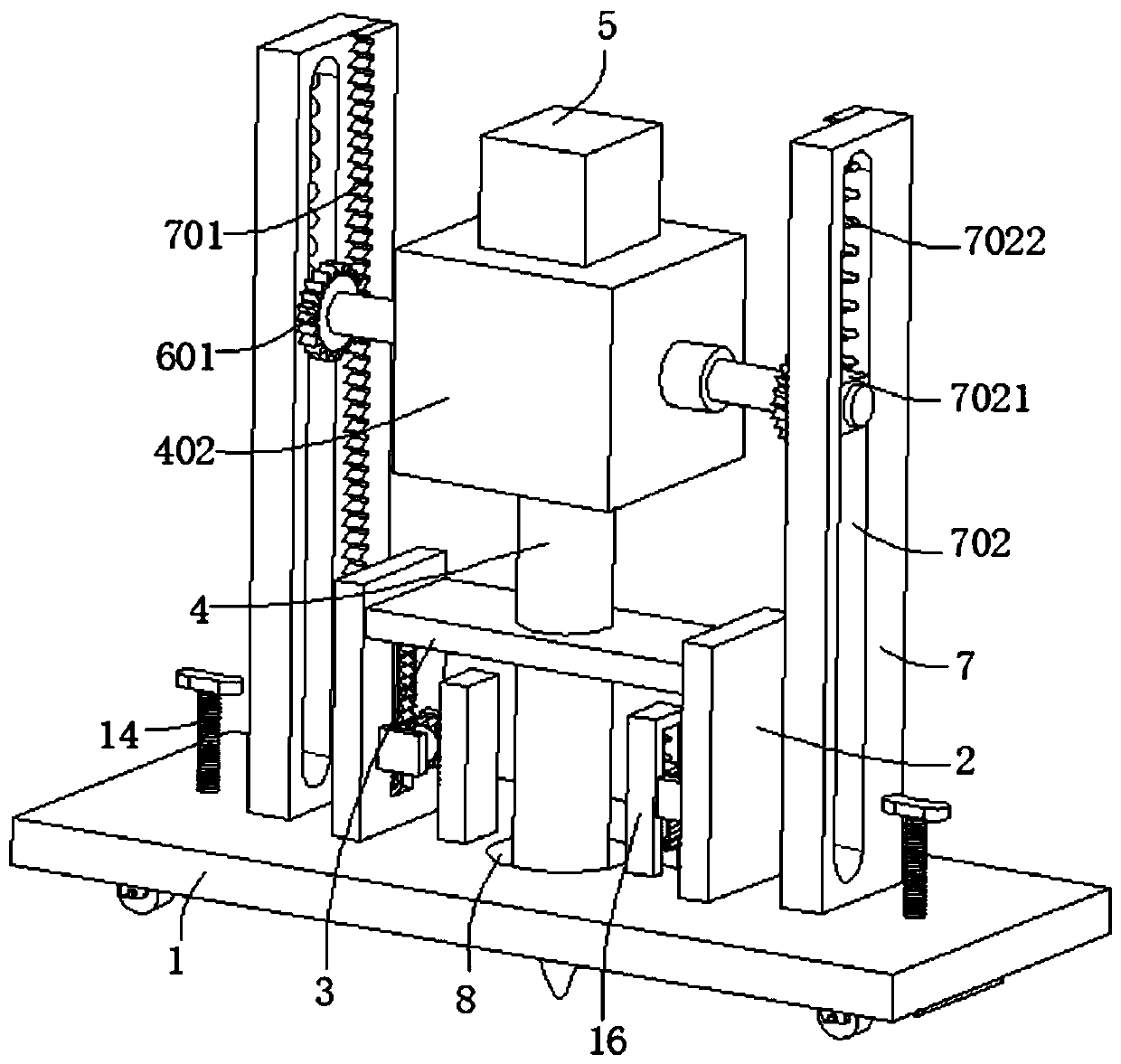
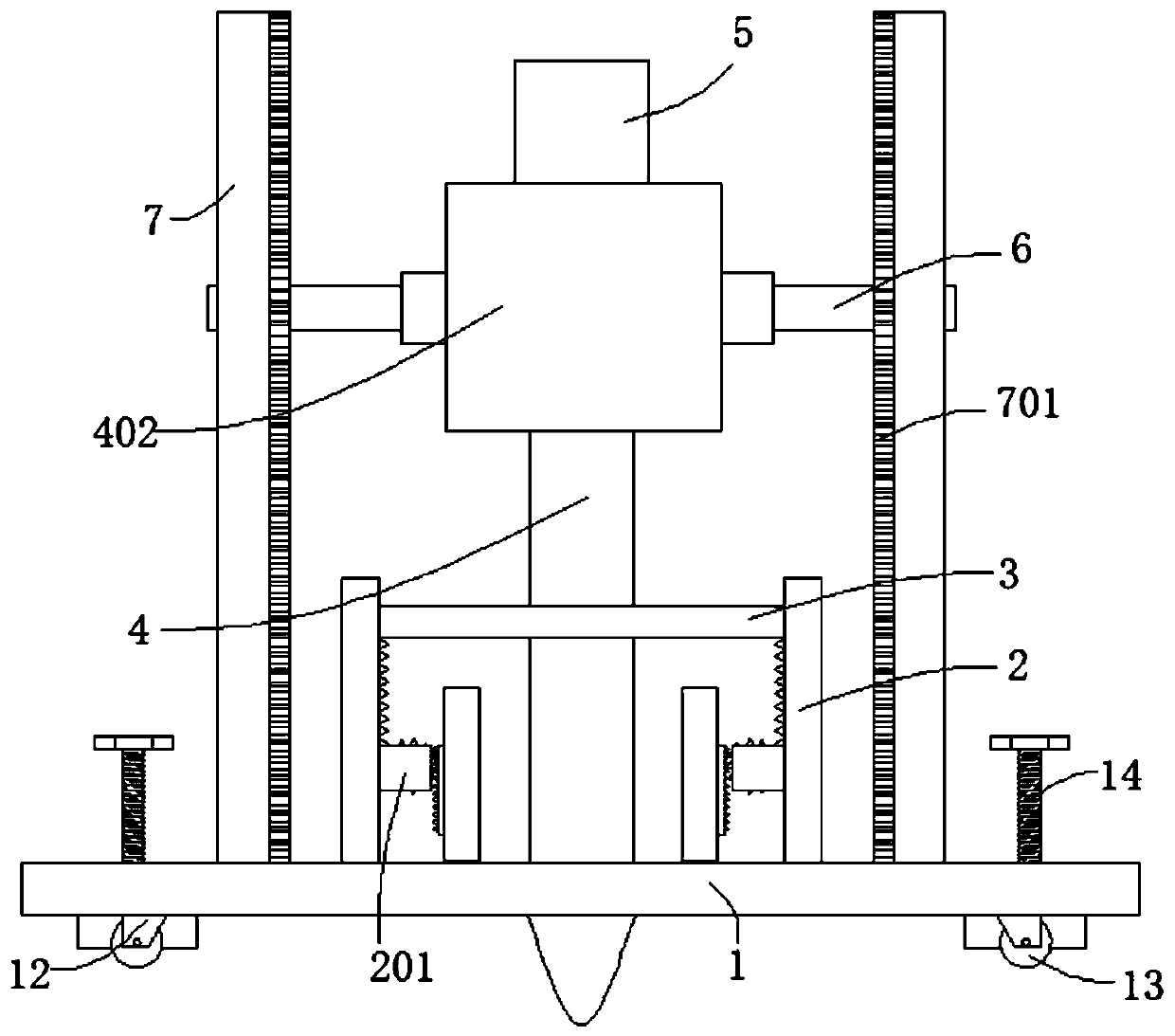
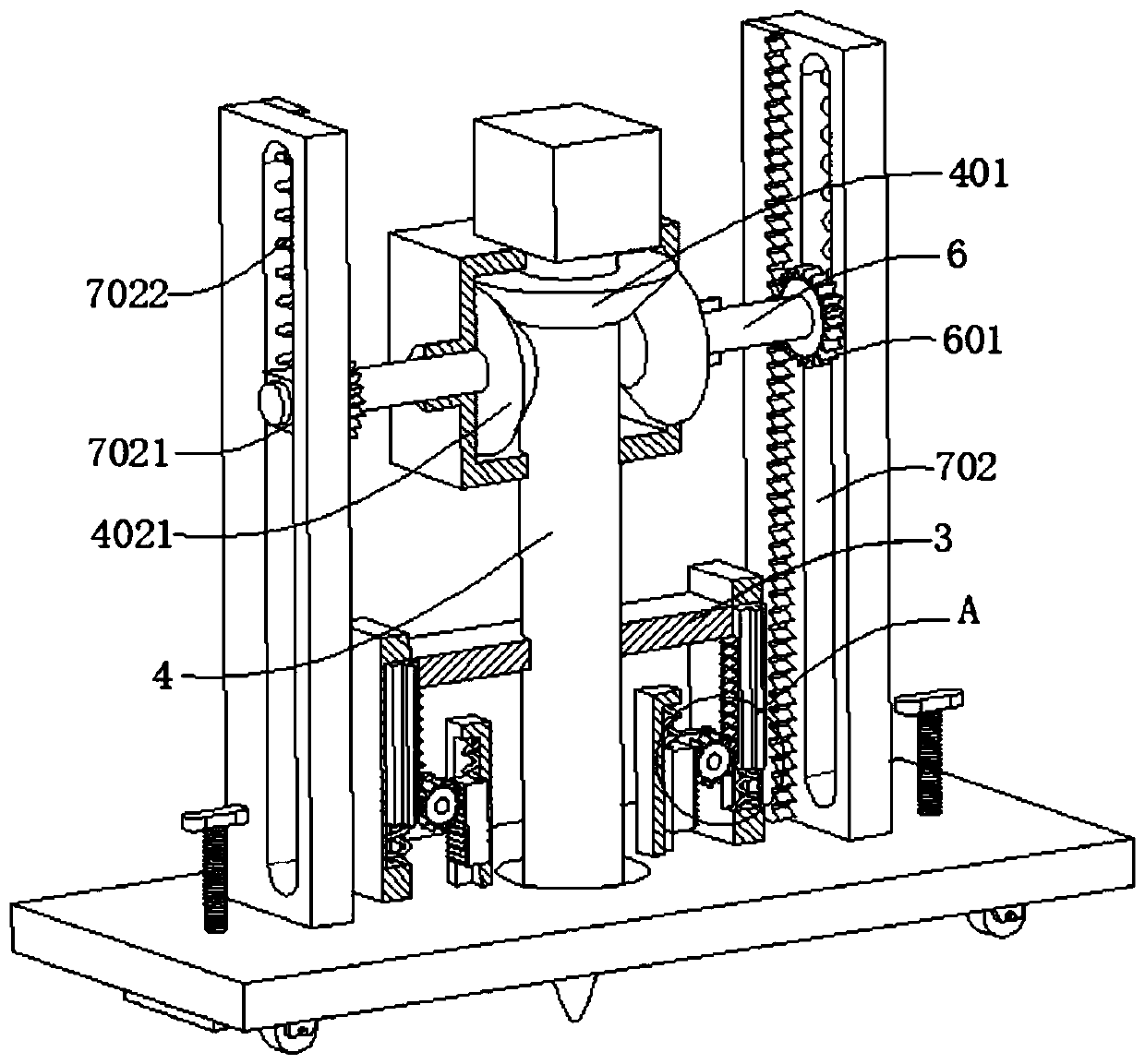
[0036] refer to figure 1 , figure 2 , image 3 and Figure 6, a drilling device for road construction, comprising a base 1, a first vertical plate 2 is connected to both sides of the top of the base 1, a shock absorbing plate 3 is connected between the two first vertical plates 2, and inside the shock absorbing plate 3 Slidingly connected with a rotating shaft 4, the outer wall of the rotating shaft 4 is rotatably connected with a casing 402 through a bearing, the outer wall of the rotating shaft 4 is connected with a first bevel gear 401, and the inner wall of the casing 402 is rotatably connected with a second bevel gear 401 that meshes with the first bevel gear 401. The bevel gear 4021 is connected with the motor 5 on the top of the box 402, the output end of the motor 5 is connected with the rotating shaft 4, and the end of the rotating shaft 4 away from the motor 5 is detachably connected with a drill bit 403, and the outer wall of the second bevel gear 4021 is connect...

Embodiment 2

[0039] refer to figure 1 , figure 2 , image 3 , Figure 4 and Figure 7 , a drilling device for road construction, which is basically the same as Embodiment 1, furthermore, the outer wall of the first vertical plate 2 is dug with a second groove 9, and the inner wall of the second groove 9 is slidably connected with a second rack plate 901, the second rack plate 901 is fixedly connected to the outer wall of the shock absorbing plate 3, and a second elastic element 902 is connected between the bottom wall of the second rack plate 901 and the inner wall of the second groove 9, and the second groove 9 The inner walls of both sides are dug with chute 903, the inner wall of chute 903 is slidably connected with slider 9011, the slider 9011 is fixedly connected with the outer wall of the second rack plate 901, and the outer wall of the first vertical plate 2 is connected with two side plates 201, A fixed rod 202 is rotatably connected between the two side plates 201, and the ou...

Embodiment 3

[0042] refer to Figure 1-7 , a drilling device for road construction, basically the same as embodiment 1, furthermore, the bottom of the base 1 is connected with a fixed block 12, the fixed block 12 is connected with a roller 13 for rotation, and the inner thread of the base 1 is connected with a threaded rod 14. The top of the threaded rod 14 is connected with a handle 141, and the end of the threaded rod 14 away from the handle 141 is connected with a connecting plate 142, and the connecting plate 142 is connected with a rotating shaft 1421 for rotation, and the outer wall of the rotating shaft 1421 is connected with a rubber block 15, and the rubber block 15 The bottom wall is provided with anti-slip lines; move the device to the area where holes need to be punched through the roller 13, and after reaching the designated position, turn the handle 141 to make the handle 141 drive the threaded rod 14 to rotate, so that the threaded rod 14 moves down relative to the base 1, so...


PUM


Abstract

The invention discloses a drilling device for road construction and a using method thereof, and belongs to the technical field of road construction equipment. The drilling device for road constructioncomprises a base, first vertical plates are connected with the two sides of the top of the base, a damping plate is connected between the two first vertical plates, a rotating shaft is slidably connected into the damping plate, a box body is rotatably connected with the outer wall of the rotating shaft through a bearing, a first bevel gear is connected with the outer wall of the rotating shaft, the inner wall of the box body is rotationally connected with a second bevel gear engaged with the first bevel gear, the top of the box body is connected with a motor, and the output end of the motor is connected with the rotating shaft. According to the drilling device for road construction, a drill bit can continuously deepen the punching depth in the punching process by only driving one motor tooperate, energy consumption is reduced, the punching cost is reduced, the workload of workers is relieved, vibration in the punching process is damped through the damping plate, and the punching precision is improved.

Description

technical field [0001] The invention relates to the technical field of road construction equipment, in particular to a drilling device for road construction and a use method thereof. Background technique [0002] At present, steel bars and pillars need to be installed during the construction of traffic roads. At this time, holes need to be drilled on the road to lay a foundation for the construction. The existing drilling methods generally use the staff to hold the drilling machine to align the drill bit with the required drilling. Drilling the area increases the labor intensity, and the vibration of the drill bit during the drilling process leads to poor stability, and it is easy to deviate the drilling position, resulting in substandard holes and affecting the road Construction Schedule. [0003] The Chinese patent with the patent number CN201721032434.5 in the prior art discloses a drilling platform for road bridge construction, including a slide plate, the top of the sl...

Claims


Application Information

Patent Timeline
Patent Type & Authority Applications(China)
IPC IPC(8): E21B7/02E21B15/00E21B3/02F16F15/06F16F15/02
CPCE21B3/02E21B7/024E21B15/00F16F15/02F16F15/06
Inventor 周伟伟
Owner 萧县众科电磁检测有限公司
Why Eureka
Try Eureka