

High-speed hydraulic drill with two engines
A hydraulic drilling rig, dual-engine technology, applied in the direction of drill pipe, drill pipe, earthwork drilling, etc., can solve the problems of heavy weight, high cost, easy to break chains, etc., achieve a high degree of automation, improve performance, increase the number of drilling holes effect of depth
- Summary
- Abstract
- Description
- Claims
- Application Information
AI Technical Summary
Problems solved by technology
Method used
Image

Examples
Embodiment Construction
[0058] Below in conjunction with accompanying drawing and embodiment the present invention will be further described:
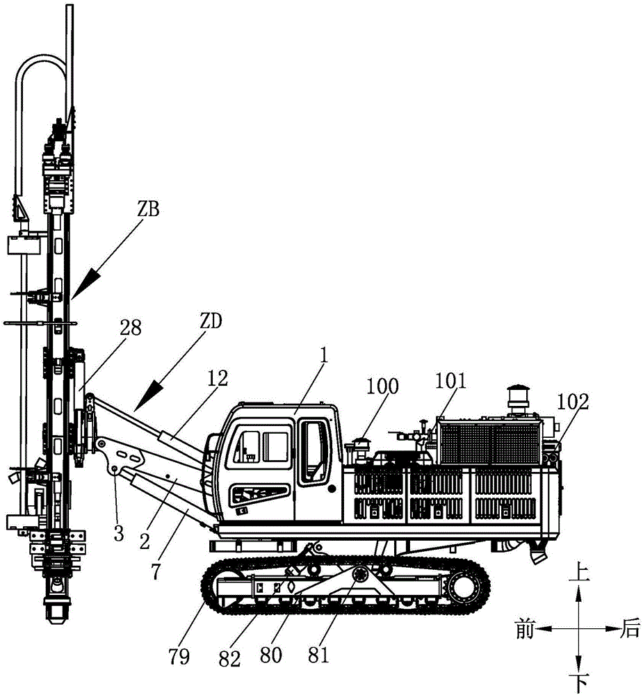
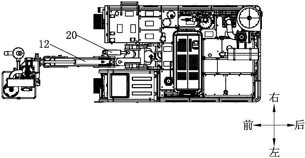
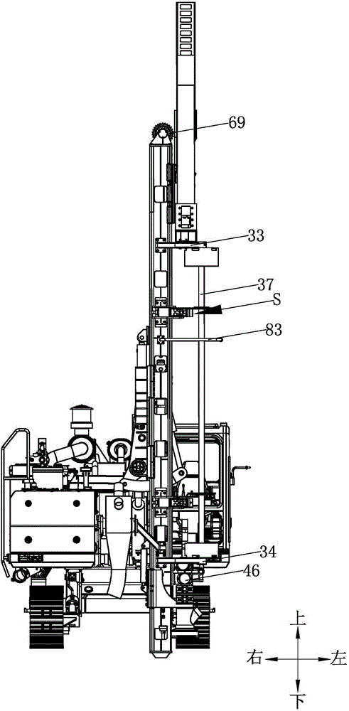
[0059] Such as figure 1 --As shown in 15, a high-speed hydraulic drilling rig with dual engines is mainly composed of a car body 1, a chassis, a straight arm assembly ZD and a drill boom assembly ZB. Wherein, two engines are installed at the car body 1 rear portion, and this car body 1 is installed on the chassis, and left crawler belt running gear and right crawler belt running gear are arranged side by side on the chassis. Moreover, an intake air filter 100 , a muffler 101 and an air compressor 102 are arranged at the rear of the vehicle body 1 , wherein the muffler 101 is located directly above the engine, and a cooler 103 is arranged laterally at the rear end of the vehicle body 1 . The structure of the left crawler belt traveling device and the right crawler belt traveling device are the same, wherein the left crawler belt traveling device comprises a l...
PUM
 Abstract
Description
Claims
Application Information