Pipe network superimposed water supply device

A technology of water supply device and pipe network, which is applied in the directions of water supply device, configuration of water supply pool and water saving, etc., can solve the problems of easily polluted water source of pool, difficult to handle equipment structure design, large building area, etc.

Inactive Publication Date: 2007-01-31
SHANGHAI KAIQUAN PUMP IND GROUP
View PDF0 Cites 8 Cited by
  • Summary
  • Abstract
  • Description
  • Claims
  • Application Information

AI Technical Summary

Problems solved by technology

The disadvantage is that it consumes a lot of energy and the water source of the pool is easily polluted.
In recent years, the newly emerging pipe network superimposed water supply equipment directly uses the municipal pipe network as the water source. Due to the airtight system, the water supply is pressurized on the basis of the municipal water pressure, and the difference is replenished. It has two advantages of hygiene and energy saving. However, the current products are also There are some problems: on the one hand, the steady flow tank that is currently used for the product is a pure water storage tank. Only when negative pressure is generated in the tank, the water volume in the tank can be effectively used to compensate for the lack of municipal water supply. The lift requirements are relatively high, which limits the overall energy-saving effect of the equipment
On the other hand, in order to retain the function of shutting down and maintaining pressure, the current product needs to install a pressure-stabilizing air tank at the outlet of the equipment, which will cause the equipment to be bulky, occupy a large building area, and the structural design of the equipment is also difficult to handle.

Method used


Image

  • Pipe network superimposed water supply device

Examples


Embodiment Construction

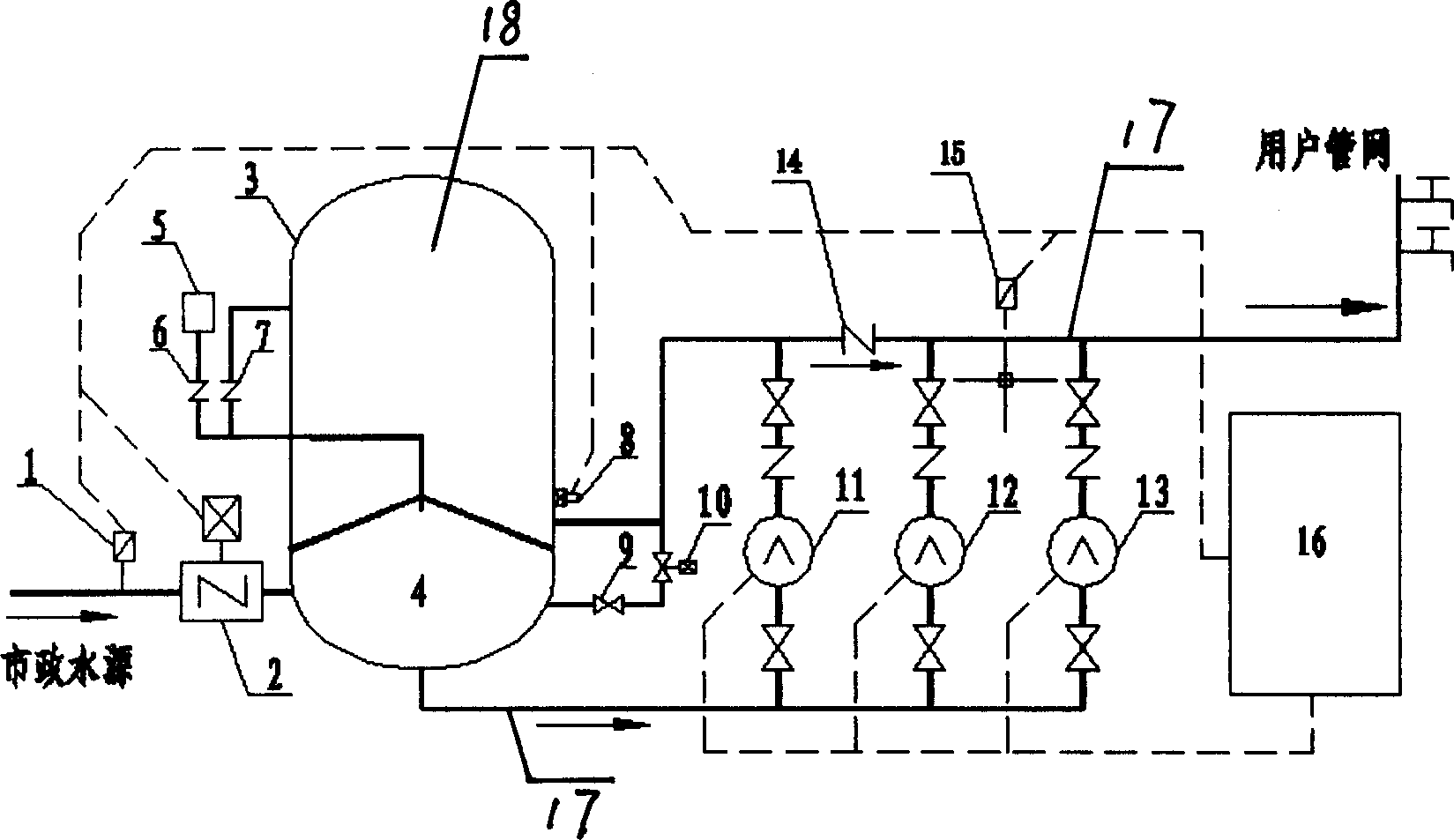
[0009] see figure 1 , the operation control mode of the equipment is as follows: debug the equipment in normal operation, and maintain the water pressure of the user pipe network by the upper compartment of the buffer tank 3 during shutdown; when the energy storage water in the upper compartment of the buffer tank 3 is used and consumed, the instrument 15 detects When the water pressure of the user's pipe network drops to the lower limit of the set pressure, and the instrument 1 detects that the water inlet pressure is normal, the equipment starts to run automatically. The compartment 4 extracts the municipal water source. On the one hand, the check valve 14 is used to supply the user pipe network with a small flow of water, and on the other hand, it also replenishes water and stores energy for the upper compartment of the buffer tank 3; if the water consumption of the user pipe network increases, the water supply pump 11 cannot If the demand is met, the second water feed pump...


PUM


Abstract

This invention relates to a automatic water supply equipment, specific to say it is a kind of pipe network press automatic water supply equipment. Its characteristic lies in that the lower isolated cavity's water inlet connects with municipal pipeline through a backflow prevention valve, the lower isolated cavity's water outlet connects with water pump unit's water inlets, and the lower isolated cavity connects with buffer tank's upper isolated cavity through the electric control valve and a flow regulating valve. The bottom of lower isolated cavity is to the outside through a passage of pipeline. This pipeline's one branch connects with the air filter through the check valve, and the other pipeline connects with buffer tank's upper cavity through the check valve. Under the buffer tank's lower cavity there sets the liquid level detector. This invention has the following advantages: a tin of much use, this is good to the equipment's structure design and contracts the equipments physical volume availably, it saves the building area and lowers the cost, what more beneficial is that it changes the buffer tank into the energy store buffer tank, this can release the storing pressure water when needed at any time and compensate the municipal's water supply.

Description

[technical field] [0001] The invention relates to automatic water supply equipment, in particular to a pipe network overlapping automatic water supply equipment. [Background technique] [0002] The traditional automatic water supply equipment is a secondary pressurized water supply equipment with a pool as the water source, and the pressure is maintained by the air pressure tank connected to the water outlet of the equipment when it is shut down. The secondary pressurized water supply equipment is simple in structure and convenient in operation and control. Its disadvantage is that it consumes a lot of energy and the water source of the pool is easily polluted. In recent years, the newly emerging pipe network superimposed water supply equipment directly uses the municipal pipe network as the water source. Due to the airtight system, the water supply is pressurized on the basis of the municipal water pressure, and the difference is replenished. It has two advantages of hygie...

Claims


Application Information

Patent Timeline
Patent Type & Authority Applications(China)
IPC IPC(8): E03B11/16E03B11/06
CPCY02A20/00
Inventor 陈英华邵耕心张素萍
Owner SHANGHAI KAIQUAN PUMP IND GROUP
Why Eureka
Try Eureka