
Impeller cylinder combination of impeller motor

An engine and impeller technology, applied in the field of impeller-cylinder combination structure, can solve the problems of no heat recovery and reuse facilities, short stroke of the piston in the cylinder, large gap between the blade and the cylinder, etc., to improve work efficiency, prevent air leakage, good reliability

Inactive Publication Date: 2007-01-31
刘天锡
View PDF1 Cites 7 Cited by
  • Summary
  • Abstract
  • Description
  • Claims
  • Application Information

AI Technical Summary

Problems solved by technology

[0002] The common problems of various internal combustion engines in the prior art are that the stroke of the piston in the cylinder is short, there is no heat energy recovery and reuse facility, and the temperature of the gas discharged after combustion is very high, which not only wastes energy, but also has adverse effects on the environment.
However, it still has the following disadvantages: 1. The gap between the blades and the cylinder in the impeller is large, and the air leakage is large; 2. Multiple sets of impellers need to be used in series to improve thermal efficiency; 3. The volume is large; it is not suitable for use on various vehicles.

Method used


Image

  • Impeller cylinder combination of impeller motor
  • Impeller cylinder combination of impeller motor
  • Impeller cylinder combination of impeller motor

Examples


Embodiment Construction

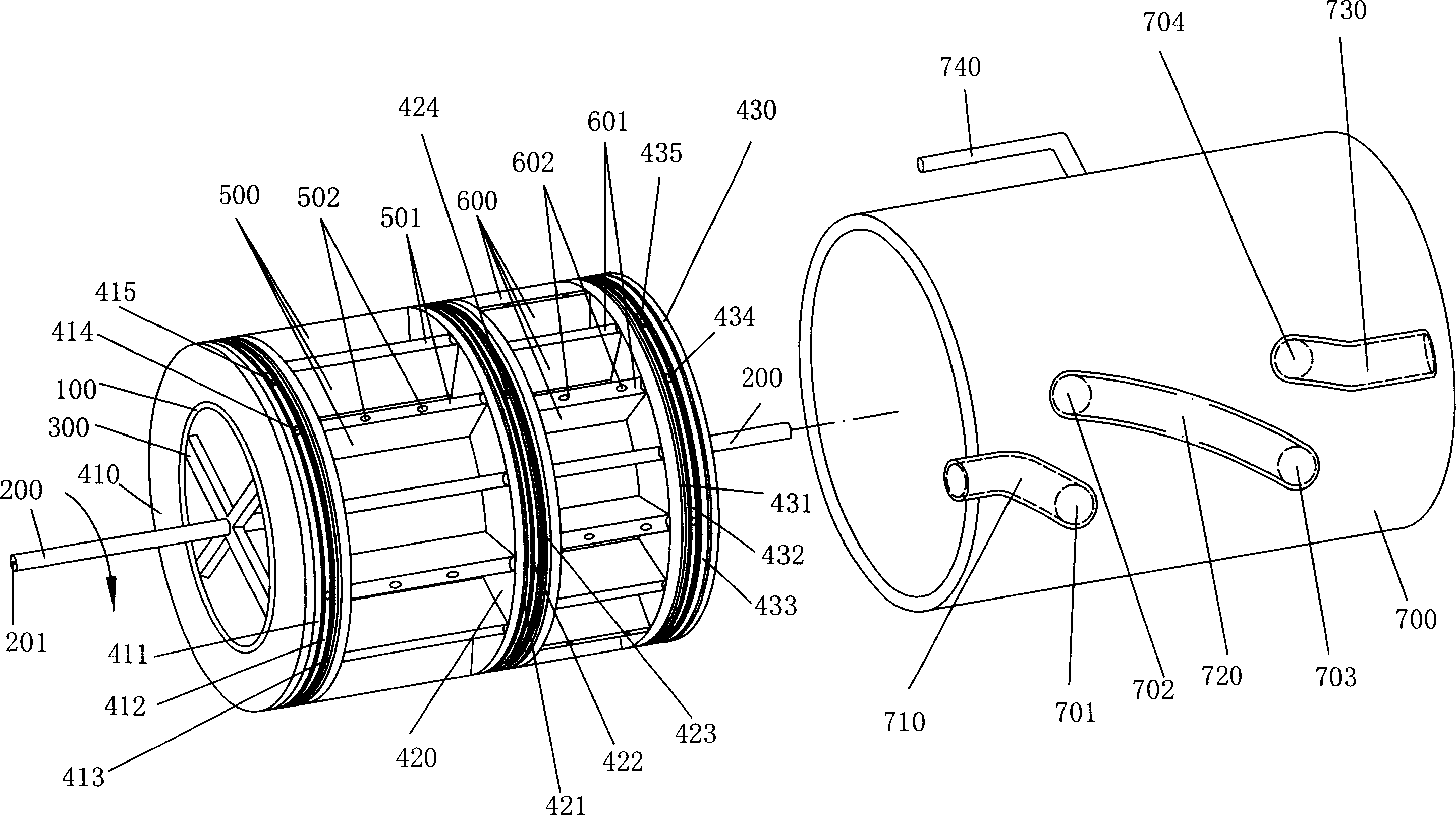
[0018] The deployment structure of an embodiment of the impeller cylinder combination of the impeller engine of the present invention, such as figure 1 shown. It consists of a cylindrical cylinder and an impeller installed in the cylinder and connected to the main shaft.

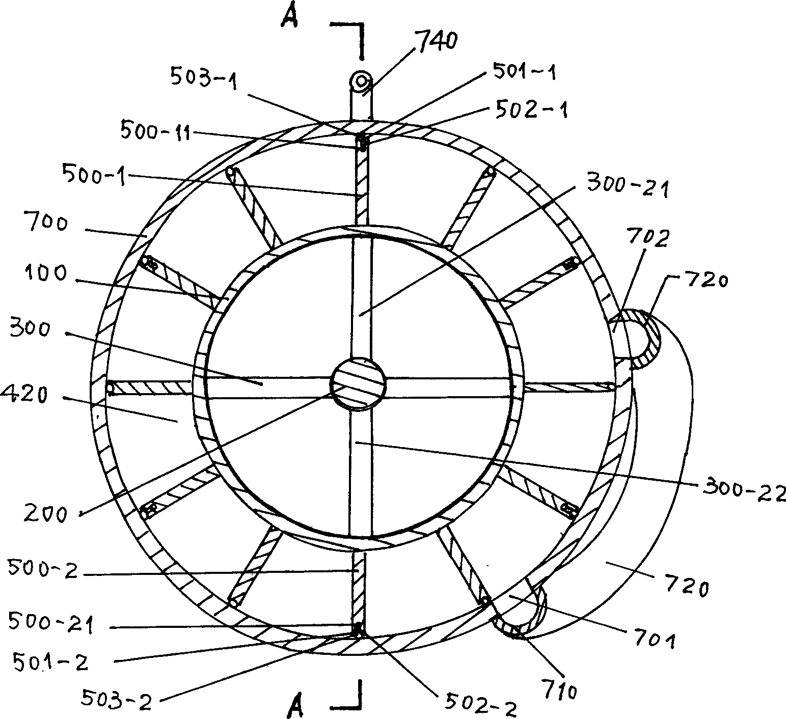
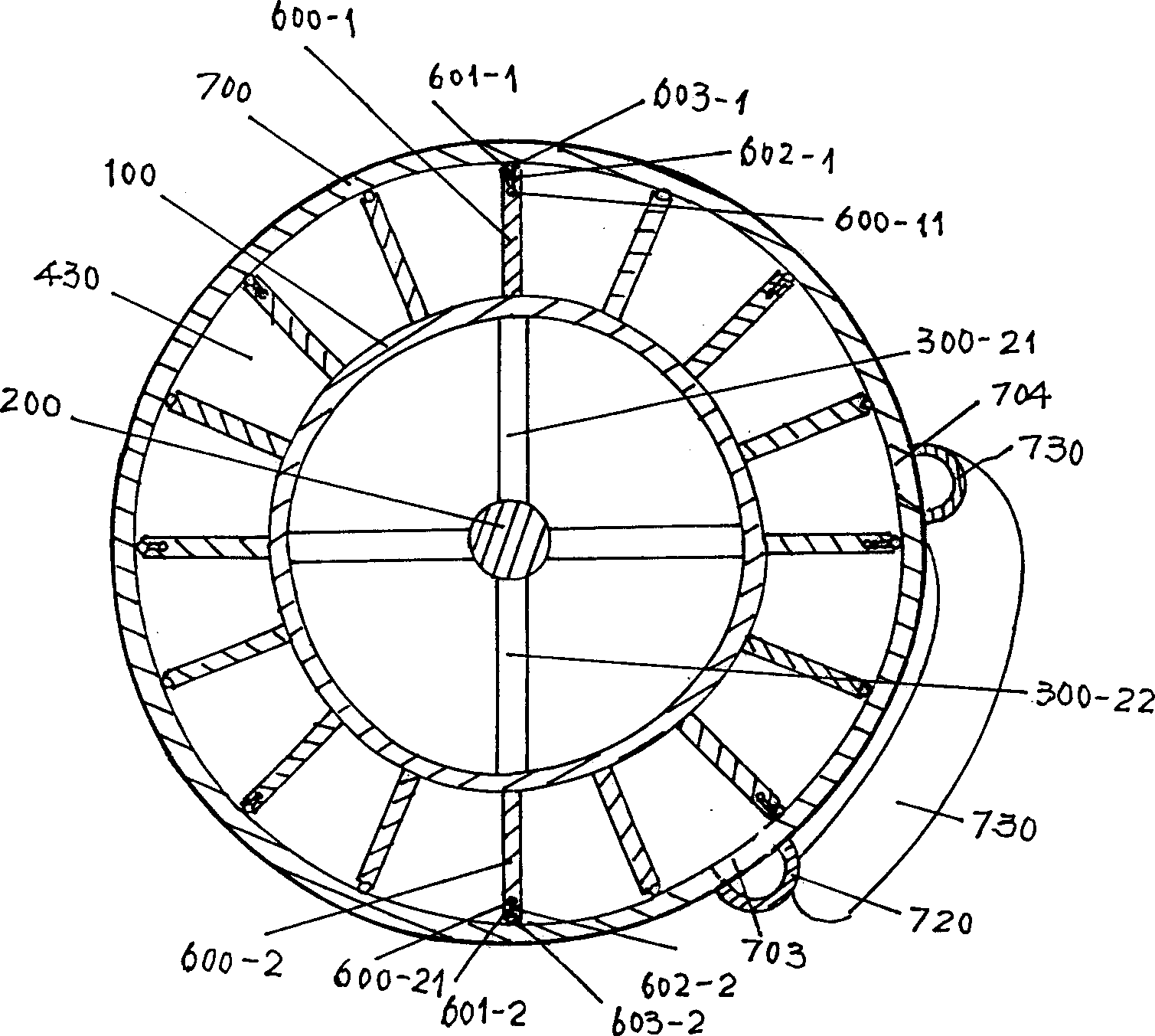
[0019] Its impeller has a cylindrical rotor 100, and four radial connecting rods 300 are evenly arranged on the inner circumference of both ends of the rotor 100 to connect the main shaft 200; The annular partitions 410, 420, 430 of the same size form two ring grooves, one wide and one narrow. Please see figure 2 , 12 radially wide vanes 500 perpendicular to the separators 410 and 420 are evenly arranged in the wider ring groove on the left; please refer to image 3 16 radially narrow blades 600 perpendicular to the separators 420 and 430 are evenly arranged in the narrower ring groove on the right side.

[0020] Please see Figure 4 The partition plate 410 at the left end of the rotor 100 is provided ...


PUM


Abstract

The invention adopts several independent gas cells formed in the cylinder by fitting the ring diaphragm on the drum rotor with the blades and they are sealed by fitting the stop ring mounted on the diaphragm with the roller pins mounted on the blades to prevent gas from leaking. By using two air passages in the cylinder divided via the middle diaphragm and connecting in series them together via a guide duct, the coaxial work of two groups of impellers can be realized in one cylinder.

Description

technical field [0001] The invention relates to an impeller-cylinder combination structure of a gas engine which blows impellers from a direction perpendicular to the main shaft. technical background [0002] The common problems of various prior art internal combustion engines are that the stroke of the piston in the cylinder is short, there is no heat energy recovery and reuse facility, and the temperature of the gas discharged after combustion is very high, which wastes energy and has adverse effects on the environment. For this reason, I proposed the technical scheme called "high-efficiency energy-saving jet engine" and applied for a Chinese utility model patent. The patent number of this utility model patent is ZL 99218233.6, which is disclosed by the Chinese utility model patent specification CN 2381791Y. I proposed to place the combustion chamber of the jet engine and the multi-stage series impellers in the heat-insulating water tank. After the fuel and compressed air ...

Claims


Application Information

Patent Timeline
IPC IPC(8): F01D1/06F01D11/08F01D25/18
Inventor 刘天锡
Owner 刘天锡
Learn More