Bimedium water electricity dual purpose heat radiator

A dual-media, radiator technology, applied in the direction of household heating, household heating, indirect heat exchangers, etc., can solve the problems of inconvenient use, waste of resources, etc., and achieve the effect of convenient use, large space occupation and simple structure

Inactive Publication Date: 2007-01-31
金帮煜
View PDF0 Cites 4 Cited by
  • Summary
  • Abstract
  • Description
  • Claims
  • Application Information

AI Technical Summary

Problems solved by technology

[0005] The present invention aims to solve the problems of inconvenient use and waste of resources existing in the prior art, and provides a dual-media, hydroelectric, and dual-purpose radiator with simple structure, convenient use, and good energy-saving effect

Method used


Image

  • Bimedium water electricity dual purpose heat radiator
  • Bimedium water electricity dual purpose heat radiator
  • Bimedium water electricity dual purpose heat radiator

Examples


Embodiment 1

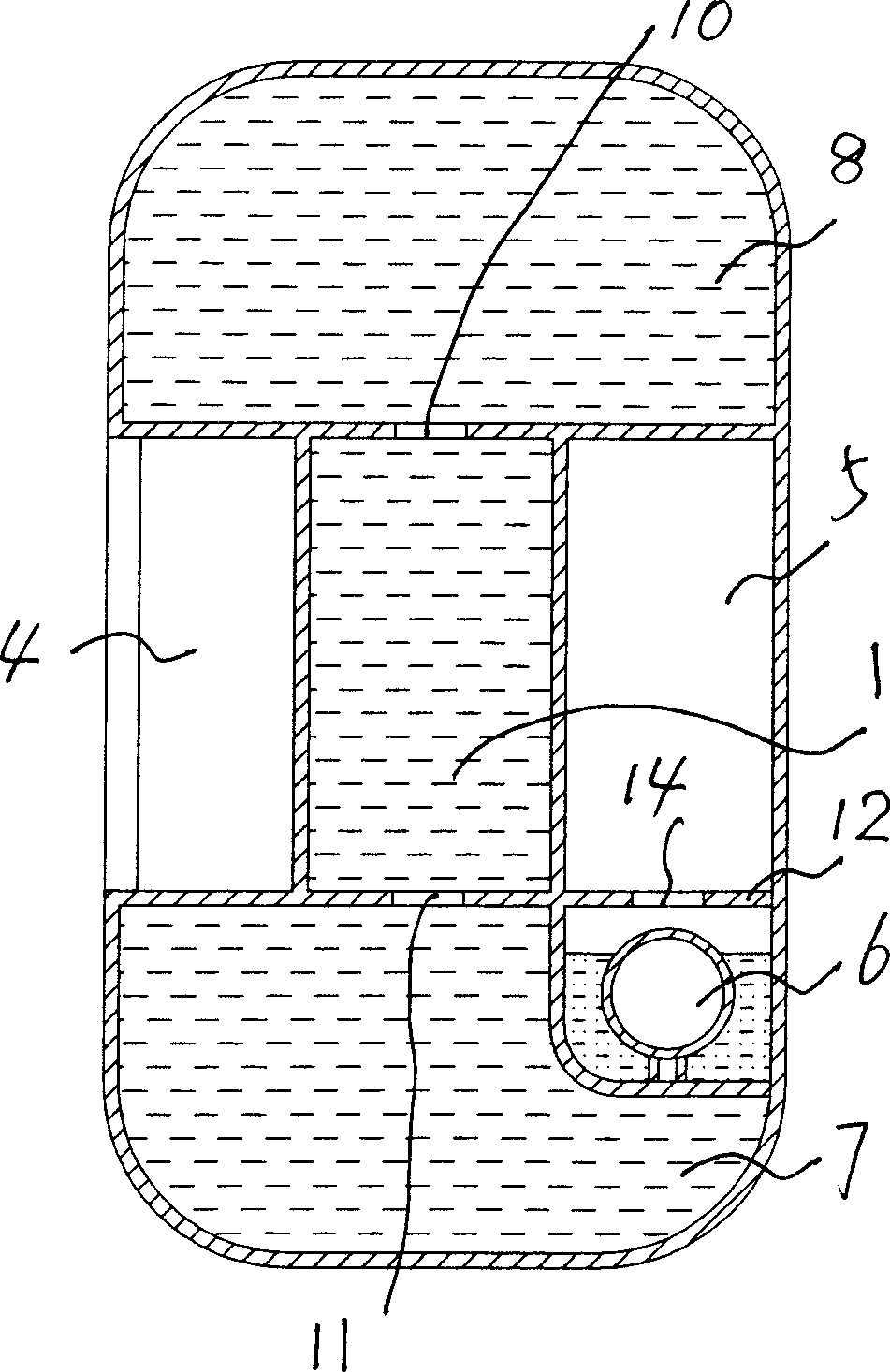
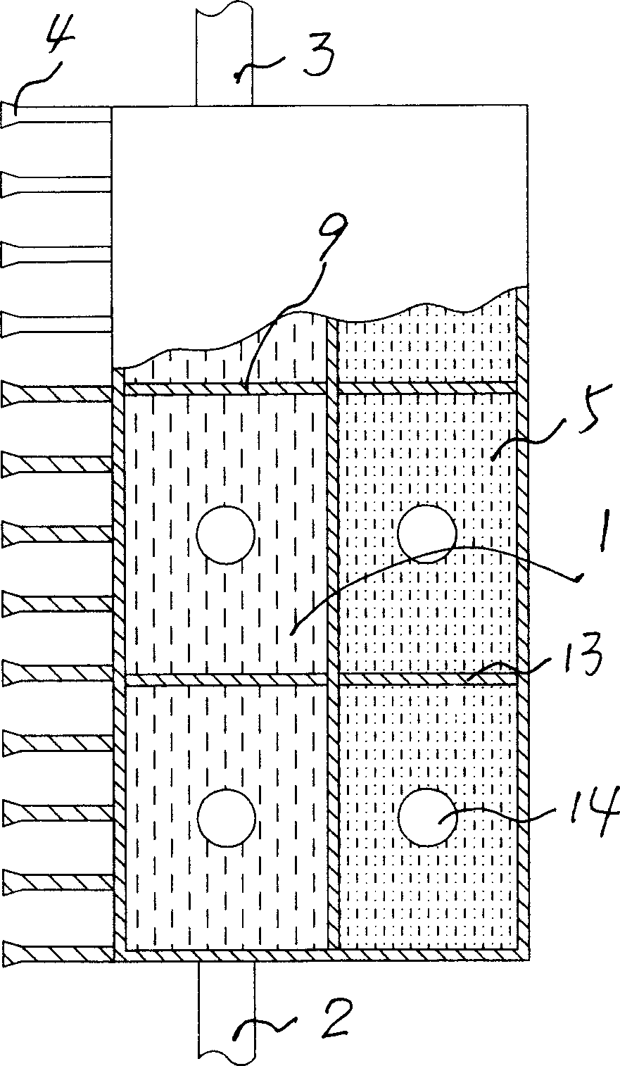
[0020] Such as figure 1 , 2 As shown: there is a water tank 1, the water tank 1 is provided with a water inlet 2 and a water outlet 3, and the water tank 1 is connected with a heat sink 4, and the water tank 1 is adjacent to a superconducting medium heating chamber 5, and the superconducting medium The lower end in the heating chamber 5 is provided with an electric heating element 6, and the electric heating element can be a resistance wire or an electric heating film or the like.

[0021] It is also possible to make the water inlet 2 communicate with the water bladder 1 through the water inlet pipe 7, and the water outlet 3 communicate with the water bladder 1 through the water outlet pipe 8, and place the outer lower end of the entire superconducting medium heating chamber 5 in the water inlet pipe 7. The superconducting medium heating chamber 5 is filled with a superconducting medium made of potassium dichromate, potassium sulfate, etc. in the prior art, and a superconduct...

Embodiment 2

[0026] Such as figure 1 , 2 , other with embodiment 1, just be provided with vertical clapboard 9 in water tank 1, have through hole 10,11 respectively on the upper and lower of the water tank 1 that is separated by vertical clapboard 9, in superconducting There are transverse partitions 12 in the medium heating chamber 5, and a plurality of vertical partitions 13 are arranged on the transverse partitions 12, and there are through holes 14 on the horizontal partitions 12 separated by the vertical partitions 13.

[0027] work process:

[0028] The hot water in the boiler enters through the water inlet 2, the water inlet pipe 7, the through hole 10, enters in each unit of the water tank 1 separated by the dividing plate 9, dissipates heat through the heat sink 4, enters the water outlet pipe 8 through the through hole 11, and then Through outlet 2, back to the boiler. In this process, the electric heating element 6 can be used to heat the superconducting medium placed in the ...

Embodiment 3

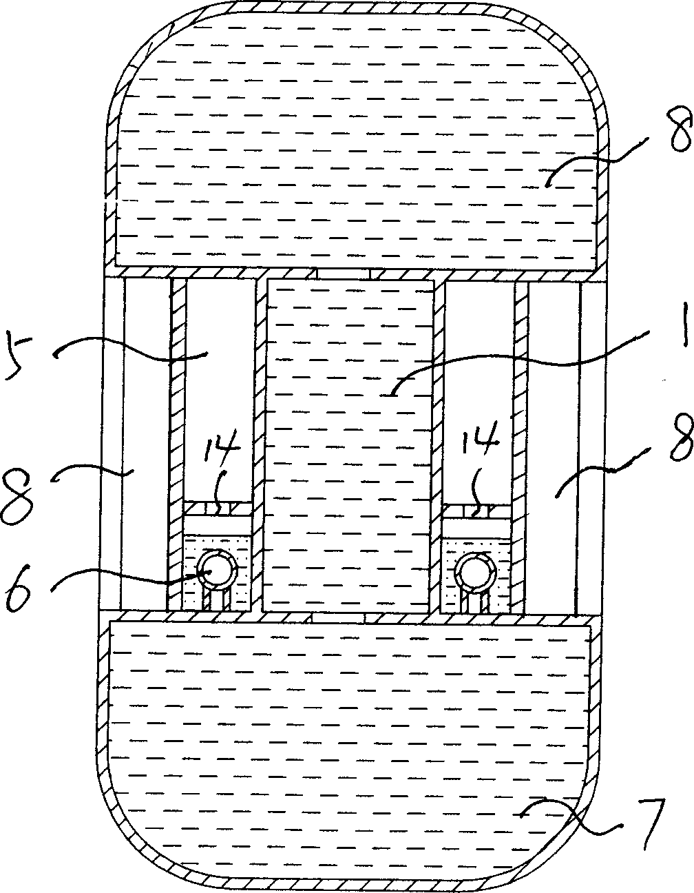
[0030] Such as image 3 Shown: there is a water tank 1, the water inlet 2 and the water outlet 3 provided by the water tank 1, the water tank 1 is connected to the cooling fin 4 through the adjacent superconducting medium heating chamber 5, and the water tank 1 in the superconducting medium heating chamber 5 The lower end is provided with electric heating element 6, and electric heating element can use resistance wire, also can use electric heating film etc. Others are basically the same as those in Embodiments 1 and 2, except that the lower end of the superconducting medium heating chamber 5 is not placed in the water inlet pipe 7 .


PUM


Abstract

The invention discloses a kind of couple medium water-electricity double-duty radiator, including a water container (1), an infall (2) and a yielding water mouth (3) on the water container (1), a radiation fin (4) connected with the water container (1), a superconducting medium heating chamber (5) and an electrical heating unit (6) in the superconducting medium heating chamber (5) and at the bottom of it. In the period of winter water heating, heat the superconducting medium through the electrical heating unit at the same time. The superconducting medium on the one hand eliminates heat through the radiation fin, on the other hand heats the hot water again. The superconducting medium possesses the advantages of low starting temperature, quick heat conduction and high thermal efficiency. So the structure not only increases the radiation effect of the radiator, but also saves a lot of fuel, decreases environmental pollution and meets the requirement of advocating using electricity nowadays. Especially when it is cold in the non-heating period, heat the superconducting medium with the electrical heating unit to obtain the purpose of heating. It is used conveniently and saves the family the incidental expenses of buying other electrical heater. It also saves the space of storing the idle electrical heater.

Description

Technical field: [0001] The invention discloses a radiator, in particular a dual-medium hydroelectric radiator with simple structure, convenient use and good energy-saving effect. Background technique: [0002] At present, heating in winter basically adopts the water heating method of water supply from the central heating boiler, that is, the heating boiler transports hot water to the radiators installed in each room for heat dissipation, so as to achieve the purpose of heating. Most of the known plumbing radiators are provided with water tanks, water inlets and water outlets connected to the water supply pipes are provided on both sides of the water tanks, and cooling fins are arranged on the front and / or rear of the water tanks. The device has the following problems: [0003] 1. Since the existing radiators can only be used for water heating, if cold weather occurs before and after the fixed heating period, most people have to take out the stored electric heaters to dispe...

Claims


Application Information

Patent Timeline
Patent Type & Authority Applications(China)
IPC IPC(8): F28D1/00F24D19/00
Inventor 金帮煜李春元周文成孙立海
Owner 金帮煜
Why Eureka
Try Eureka