
Air gap eccentric checking device and method for single-phase inductor

A technology of air gap eccentricity and detection devices, which is applied in the direction of measuring devices, electromechanical devices, asynchronous induction motors, etc., can solve the problems of large and different eccentricity, and cannot judge qualified products, etc., and achieve the effect of reliable judgment

Active Publication Date: 2007-01-31
MITSUBISHI ELECTRIC CORP
View PDF2 Cites 12 Cited by
  • Summary
  • Abstract
  • Description
  • Claims
  • Application Information

AI Technical Summary

Problems solved by technology

[0015] For example, if the eccentricity is measured with the 0-degree phase in Figure 28(a), even if it is judged as a qualified product due to the small eccentricity, if the 180-degree phase in Figure 28(b) is used to measure the eccentricity, the eccentricity The amount is relatively large, so it cannot be judged as a good product. According to the above, there is a problem that the judgment result is different according to the phase of the rotor 103.

Method used


Image

  • Air gap eccentric checking device and method for single-phase inductor
  • Air gap eccentric checking device and method for single-phase inductor
  • Air gap eccentric checking device and method for single-phase inductor

Examples


Embodiment Construction

[0053] Implementation form 1.

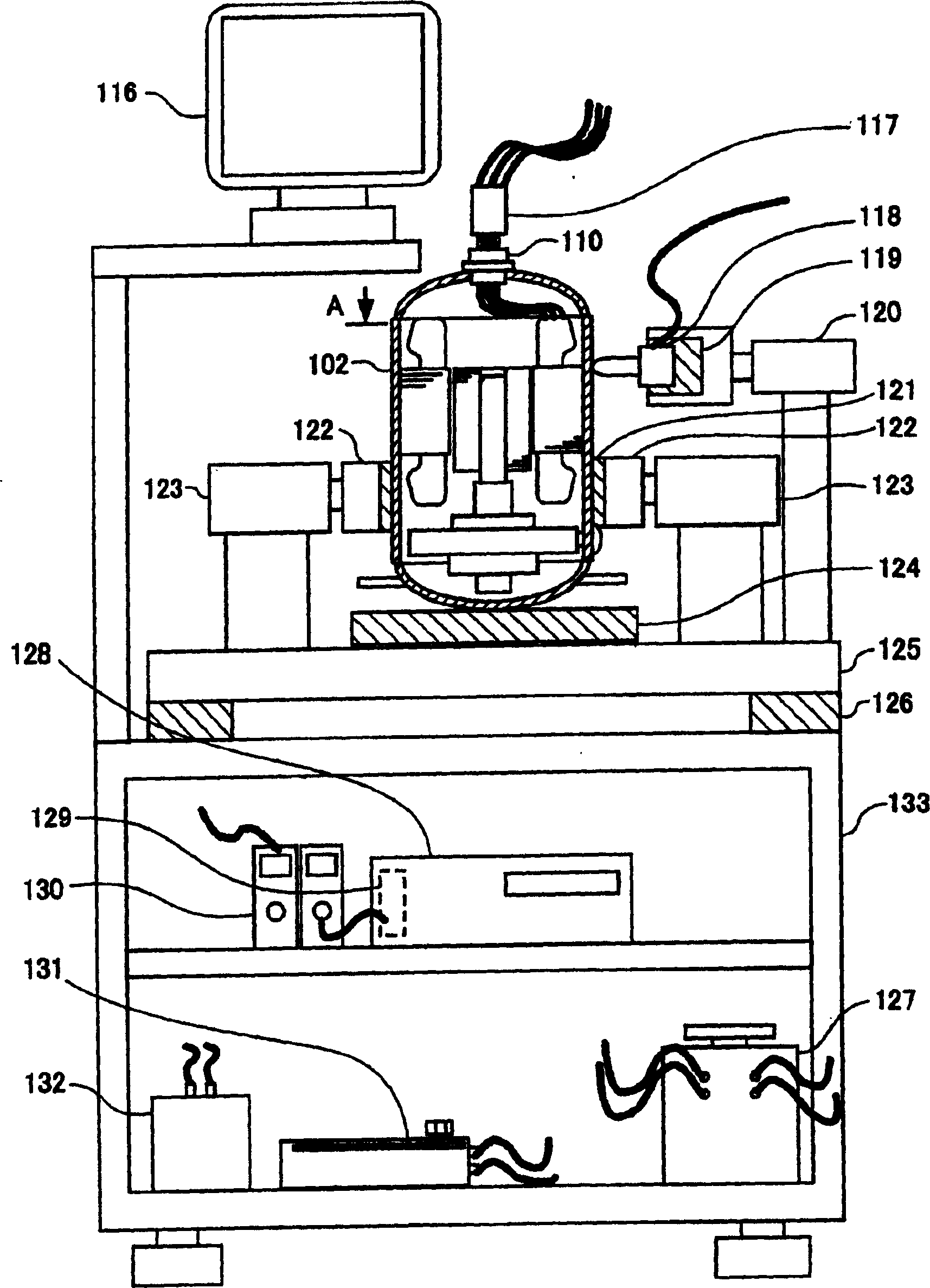
[0054] Referring to the accompanying drawings, the air gap eccentricity inspection method and air gap eccentricity detection device based on the single-phase induction machine of the present invention will be described in detail.

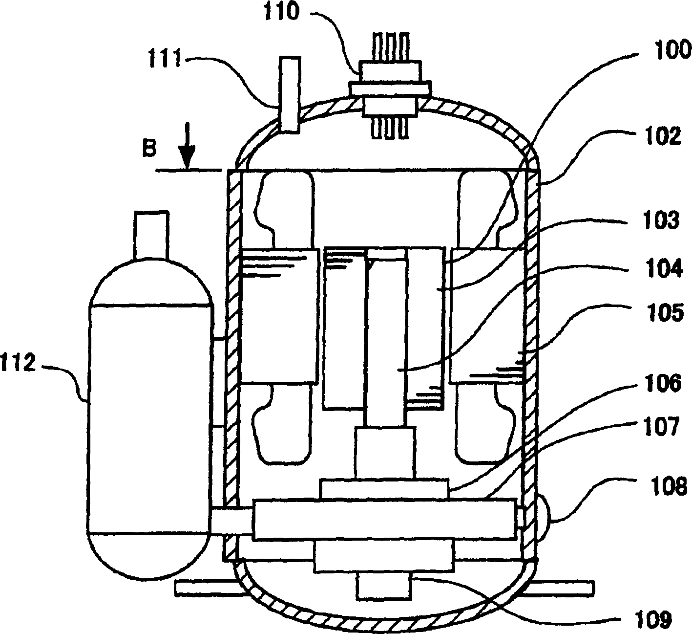
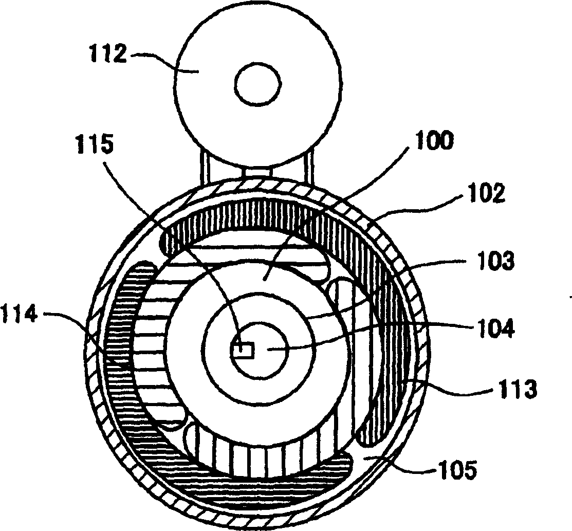
[0055] exist figure 1 shows a longitudinal cross-sectional view of a compressor for refrigeration and air conditioning with a built-in single-phase induction machine as an example of a product to which the present invention is applied. figure 2 From figure 1 The cross-sectional view of the arrow B seen.

[0056] In the drawing, 103 and 105 denote a rotor and a stator which are main components of a single-phase induction machine, and an air gap 100 exists in a cylindrical space between the rotor 103 and the stator 105 . The stator 105 is fixed on the casing 102 as a pressure vessel by sintering, and the rotor 103 and the main shaft 104 are fixed as a whole by sintering. The main shaft 104 is supported by sliding...


PUM


Abstract

By measuring the air gap eccentricity and eccentric direction during the rotor rotation, it is possible to accurately determine whether the air gap is qualified or not. It can adjust the AC current flowing through the above-mentioned main coil or auxiliary coil and use a rotating magnetic field in which the magnetic flux induced by the main coil in the air gap is larger than the magnetic flux induced by the auxiliary coil in the air gap or by the auxiliary coil in the air gap. The magnetic flux induced in the gap is larger than the magnetic flux induced by the main coil in the air gap. The rotating magnetic field causes the rotor to rotate at a rotation period smaller than the period of the alternating current. The vibration detection sensor is installed in the direction perpendicular to the winding direction of the coil whose magnetic flux is larger than the other, and by detecting the amplitude or shape of the vibration waveform of the vibration obtained during rotational driving, the above-mentioned change according to the phase of the rotor can be calculated. Air gap eccentricity and air gap eccentric direction.

Description

technical field [0001] The invention relates to an air gap eccentricity detection device and an air gap eccentricity detection method of a single-phase induction machine. Background technique [0002] In the past, in order to detect the eccentric state of the air gap of a single-phase induction machine, for example, the following method is known according to Patent Document 1 (Japanese Unexamined 60-152262) or Patent Document 2 (Japanese Unexamined Hei 6-284655): A low voltage is applied to one of the main coil or the auxiliary coil, and the motor is not rotated to become a constrained state (also called a single-phase locked state). The vibration generated in the constrained state is detected from the radial direction of the stator. From the obtained vibration waveform and the applied voltage waveform to calculate the air gap eccentric state. [0003] In general, single-phase induction motors such as Figure 23 In such a configuration, a main coil 10 (solid line) and an au...

Claims


Application Information

Patent Timeline
IPC IPC(8): H02K17/30H02K15/16G01R31/34G01B21/16
Inventor 国分忍岩崎俊明浮冈元一
Owner MITSUBISHI ELECTRIC CORP
Learn More