Low delay temp compensation bias circuit for TDD mode

A technology of temperature compensation and time-division duplexing, which is applied to improving amplifiers to reduce temperature/power supply voltage changes, electrical components, transmission systems, etc. It can solve problems such as large time constants, uncertainties, and insufficient compensation to achieve electrical performance. Effects of unaffected and stable bias voltage

Active Publication Date: 2007-01-31
SHANGHAI MUNICIPAL ELECTRIC POWER CO
View PDF0 Cites 7 Cited by
  • Summary
  • Abstract
  • Description
  • Claims
  • Application Information

AI Technical Summary

Problems solved by technology

[0014] According to the characteristics of the RF amplifier, when the temperature changes, it is expected to generate dV d The compensation amount of / dt, but, as can be seen from (2), the first item has uncertainty; due to the effect of a factor (1-η), the compensation amount of the second item is not enough
Therefore, the compensation effect of this method is not very ideal
[0015] 2. It is difficult to balance the relationship between the filtering, decoupling, voltage stabilization of the circuit and the time delay of the feed voltage
If there is a capacitance of uF level in the filter, the time constant will be very large, reaching tens of us, which is unacceptable in a TDD system
If the value of the capacitor is reduced, or the value of the potentiometer is reduced, the adjustable range of the voltage may not be enough. In addition, the effect of filtering and voltage stabilization is not very good.
[0017] Therefore, in such a circuit, it is difficult to simultaneously satisfy the relationship between the filtering, decoupling, voltage stabilization of the circuit and the time delay of reducing the feed voltage

Method used


Image

  • Low delay temp compensation bias circuit for TDD mode
  • Low delay temp compensation bias circuit for TDD mode

Examples


Embodiment Construction

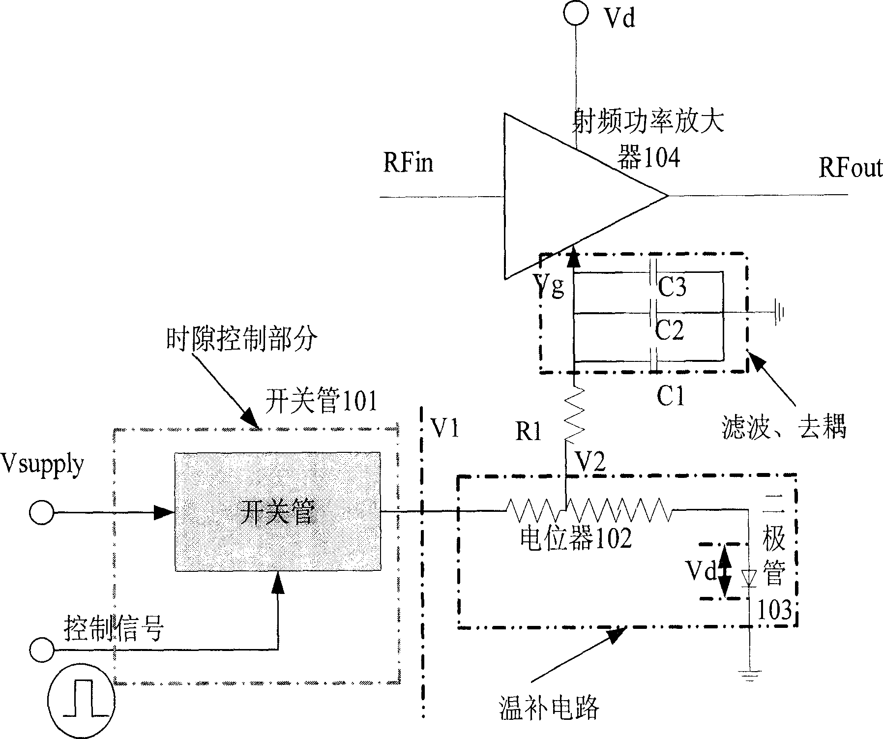
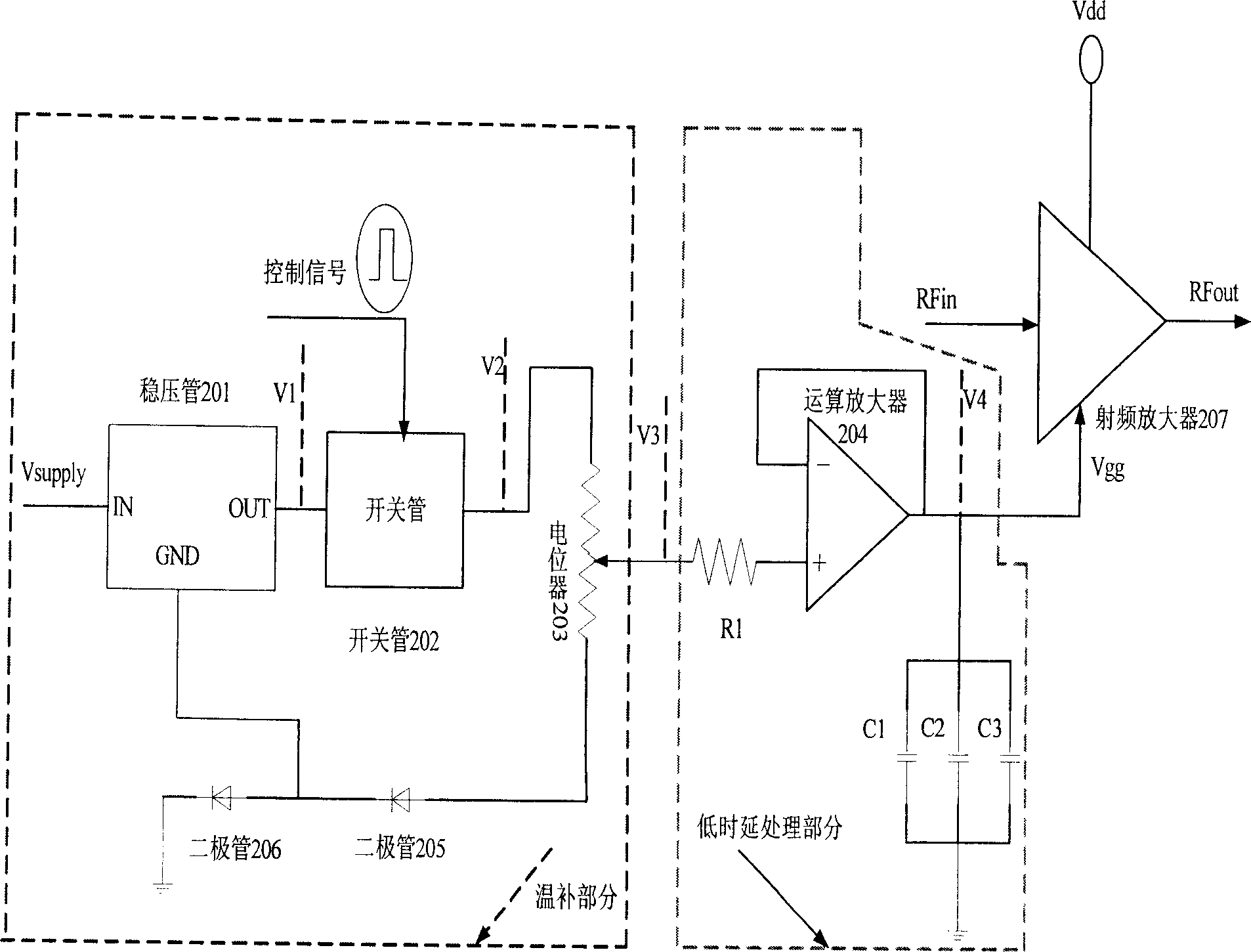
[0033] figure 2 A schematic diagram of the low-latency temperature compensation bias circuit for TDD mode of the present invention is shown.

[0034] Such as figure 2 As shown, the low time-delay temperature compensation bias circuit of the present invention is mainly composed of a voltage regulator tube, a switch tube, a potentiometer, an operational amplifier and a diode.

[0035] The circuit consists of two parts, the temperature compensation part formed by the closed loop circuit in front of V3, and the low delay processing part between V3 and Vg.

[0036] from figure 2 It can be seen that the input voltage Vsupply passes through the regulator tube 201 to generate a stable voltage V1, and when the ambient temperature changes, the voltage remains basically unchanged, reducing the instability of the subsequent circuit voltage. The voltage V1 is input into the switch tube 202, and under the action of the control signal (TTL signal), a pulse voltage V2 that changes with ...


PUM


Abstract

The invention provides a low-delay temperature compensation biasing circuit for time division duplexing mode, comprising: switch tube; potentiometer, one end connected with output end of the switch tube, voltage dividing output end passing through series-connected resistor and filter decoupling circuit and acting as output bias voltage, and another end earthed through temperature compensation diodes; the temperature compensation diodes comprise series-connected first and second diodes; the input voltage is inputted into a voltage stabilizing tube and then outputted to the switch tube, the earth end of the voltage stabilizing tube is connected in between the first and second diodes; a negative feedback amplifier is connected in series between the series-connected resistor and filter decoupling circuit. And it compensates bias voltage of the amplifier, makes the static current of the amplifier keep constant and electric performance not influenced.

Description

technical field [0001] The invention relates to a temperature compensation bias circuit, in particular to a low time delay temperature compensation bias circuit for time division duplex mode. Background technique [0002] In the operation of the communication system, when the ambient temperature changes, the temperature in the system will also change accordingly, and the temperature of the corresponding amplifying unit will also increase or decrease (especially for the power amplifier of the transmitting part), resulting in power amplifier The junction temperature rises or falls. As the junction temperature changes, various parameters of the power amplifier will also change accordingly, which will lead to changes in the quiescent current of the power amplifier. other systems. [0003] In a system working in TDD (Time Division Duplex) mode, the transmission and reception of signals are separated in time, so it is necessary to control the time slots of the transmitting circu...

Claims


Application Information

Patent Timeline
Patent Type & Authority Applications(China)
IPC IPC(8): H03F1/30H04B1/40
Inventor 鄢良才田其
Owner SHANGHAI MUNICIPAL ELECTRIC POWER CO
Why Eureka
Try Eureka