Abnormality diagnosis device and abnormality diagnosis method

A fault diagnosis device and fault technology, applied in the direction of measuring device, shaft and bearing, bearing, etc., can solve problems such as waste of cost, large amount of labor, omission of defects, etc.

Inactive Publication Date: 2007-01-31
NSK LTD
View PDF18 Cites 69 Cited by
  • Summary
  • Abstract
  • Description
  • Claims
  • Application Information

AI Technical Summary

Problems solved by technology

In addition, as major defects found through inspection, in the case of bearings, there are indentations by erosion of impurities, and exfoliation due to rolling fatigue or other wear, etc., and in the case of gears, there are teeth Chipping, wear, etc. of parts, in the case of wheels, there is grinding, etc., and in any case, when dents and protrusions, wear, etc., which do not exist in a new product are found, replace the product with a new one
[0003] However, in the method of dismantling the entire machine equipment and inspecting it by optical observation by a person in charge, in the dismantling operation of removing the rotating part or sliding part from the device, or in reintegrating the rotating part or sliding part In the operation of the inspection, a

Method used


Image

  • Abnormality diagnosis device and abnormality diagnosis method
  • Abnormality diagnosis device and abnormality diagnosis method
  • Abnormality diagnosis device and abnormality diagnosis method

Examples


no. 1 example

[0261] First, refer to Figure 1 to Figure 6 A fault diagnosis device according to a first embodiment of the present invention will be described.

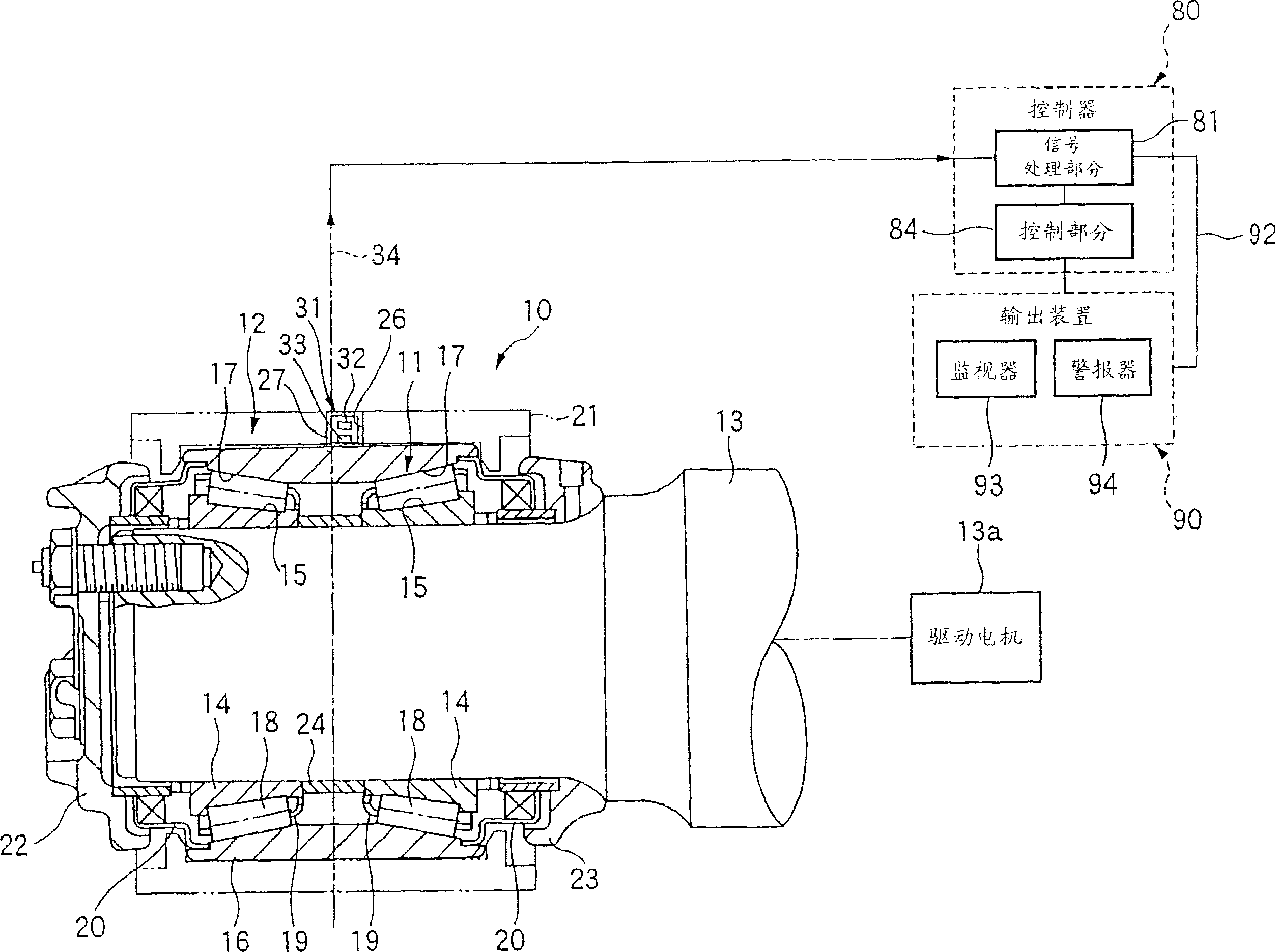
[0262] Such as figure 1 As shown, a rolling bearing device 10 of a railway vehicle including machine equipment to which a fault diagnosis device is applied includes: a double-row tapered roller bearing 11 forming a rotating part; and a bearing housing 12 forming a frame (carriage) of a railway vehicle ) part of the static member. In addition, the fault diagnosis device includes: a detection part 31 for detecting a signal generated from the rolling bearing device 10; a controller 80 including a signal processing part 81 for determining the double row cone The failure state of the roller bearing 11, etc.; the control part 84, which is used to control the driving of the rolling bearing device 10; and the output device 90 of the monitor 93, the alarm 94, and the like.

[0263] This double-row tapered roller bearing 11 includes a pai...

no. 2 example

[0289] Next, refer to Figure 7 and Figure 8 A fault diagnosis device according to a second embodiment of the present invention will be described in detail. In addition, parts equivalent to those in the first embodiment are attached with the same symbols, and descriptions thereof will be omitted or simplified.

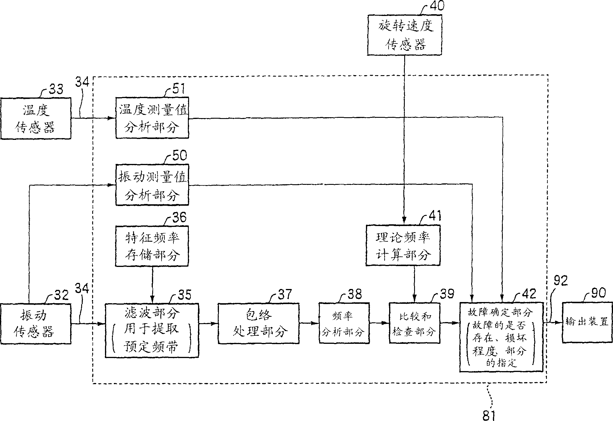
[0290] According to the present embodiment, based on the shut-off signal of the drive motor 13a, and the rotation speed sensor 40, the signal processing section 81 detects that the drive motor 13a is not turning toward the drive motor 13a (see figure 1 ) state of the double-row tapered roller bearing 11 that is rotated by inertia within a predetermined rotation speed range when energized, and at the time of detection, the double-row tapered roller bearing 11 is diagnosed based on the detection signals of the vibration sensor 32 and the temperature sensor 33 failure.

[0291] First, if Figure 7 As shown, after amplification and A / D conversion, the vibration signal...

no. 3 example

[0301] Next, refer to Figure 9 A fault diagnosis device according to a third embodiment of the present invention will be described. In addition, parts equivalent to those in the second embodiment are attached with the same symbols, and descriptions thereof will be omitted or simplified.

[0302] According to the fault diagnosis device of this embodiment, such as Figure 9 As shown in the flowchart of the rotation state determining part 52 (refer to Figure 7 ) to determine whether the rotation speed information of the double-row tapered roller bearing 11 from the rotation speed sensor 40 falls at a value equal to or faster than 100 min -1 And equal to or slower than 1500min -1 within the rotation speed range (step S21). In addition, when the rotation speed information of the double row tapered roller bearing 11 is equal to or faster than 100min -1 And equal to or slower than 1500min -1 When the rotation speed is out of the range, the operation returns to step S21 to rep...


PUM

PropertyMeasurementUnit
Outer diameteraaaaaaaaaa
The inside diameter ofaaaaaaaaaa

Abstract

An abnormality diagnosis device used for a machine apparatus having a part rotating and sliding relative to a stationary member is provided with a detection section (31) and a signal processing section (81). The detection section (31) is fixed to the part rotating or sliding or to the stationary member and has a vibration sensor (32) and a temperature sensor (33). The signal processing section (81) determines the condition of the part based on a signal detected and outputted by the detection section (31). The signal processing section (81) determines whether there is an abnormality in the part, or whether there is an abnormality in the part and the degree of damage of the part.

Description

technical field [0001] The present invention relates to a fault diagnosis device and a fault diagnosis method for rotating or sliding parts of machine equipment such as shafts or gearboxes of railway vehicles or reduction gears of wind power generators. Specifically, the present invention relates to a fault diagnosis device and a fault diagnosis method for specifying the presence or absence of a fault or a symptom of a fault of a component, or a faulty part thereof. Background technique [0002] Traditionally, in rotating parts of railway vehicles, wind generators, etc., bearings or other rotating parts are regularly inspected for damage, wear, etc. after a constant period of use. Periodic inspections are carried out by dismantling the machine equipment integrated with the rotating parts, and the damage or wear occurring at the rotating parts is found through the optical observation inspection by the person in charge. In addition, as major defects found through inspection, ...

Claims


Application Information

Patent Timeline
IPC IPC(8): G01M19/00G01M13/04G01H17/00F16C19/52G01M99/00
Inventor 宫坂孝范武藤泰之佐原淳太郎
Owner NSK LTD
Why Eureka
Try Eureka