Carbon nano-tube preparation method and apparatus

A technology of carbon nanotubes and preparation devices, which is applied in the direction of nanostructure manufacturing, nanotechnology, nanotechnology, etc., and can solve the problems of different lengths of carbon nanotubes, inconsistent emission electron characteristics of carbon nanotubes, and poor brightness uniformity of displays, etc. problem, to achieve the effect of uniform length

Inactive Publication Date: 2007-02-07
HONG FU JIN PRECISION IND (SHENZHEN) CO LTD +1
View PDF0 Cites 13 Cited by
  • Summary
  • Abstract
  • Description
  • Claims
  • Application Information

AI Technical Summary

Problems solved by technology

[0004] However, the carbon nanotubes prepared by this method have different lengths, which leads to inconsistent electron emission characteristics of carbon nanotubes.
If this carbon nanotube is applied to a field emission display, it may lead to poor brightness uniformity of the field emission display

Method used


Image

  • Carbon nano-tube preparation method and apparatus
  • Carbon nano-tube preparation method and apparatus
  • Carbon nano-tube preparation method and apparatus

Examples


no. 1 example

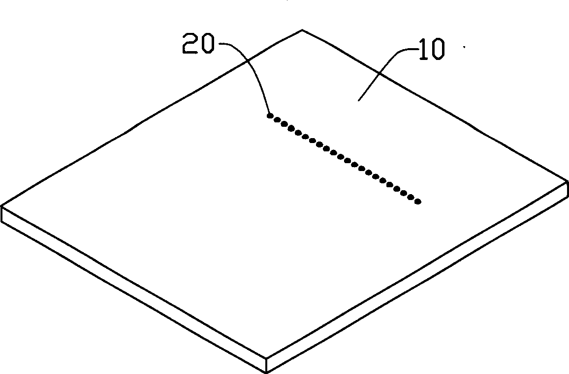
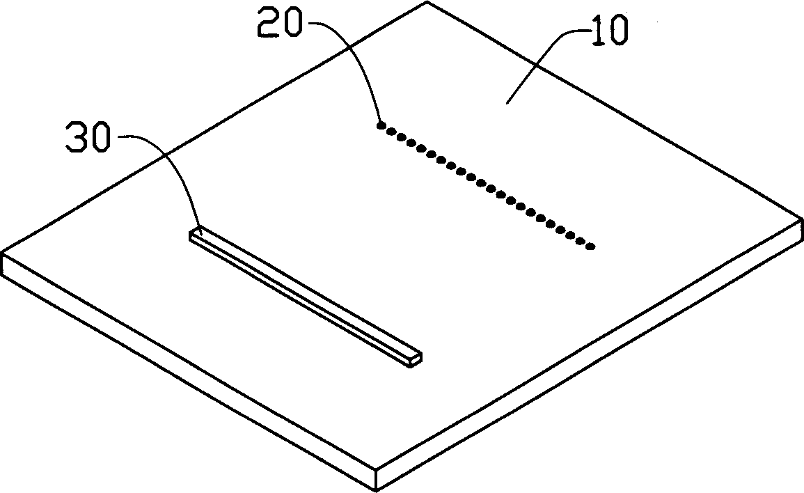
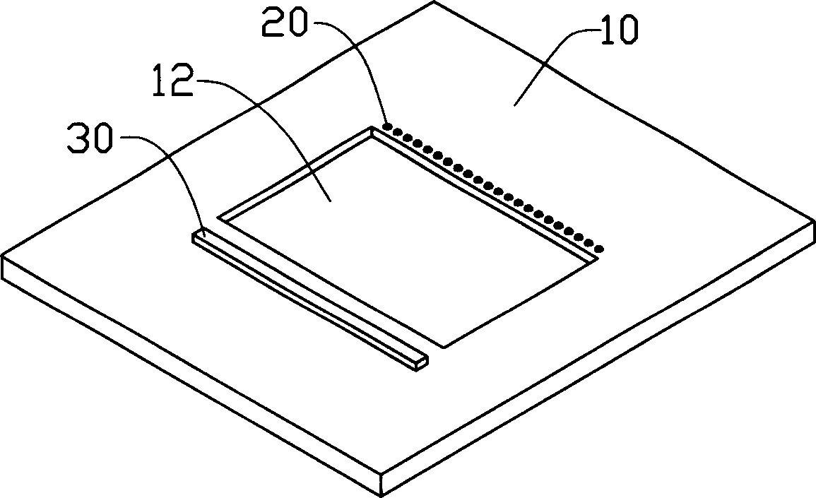
[0035] see Figure 1 to Figure 4 , the first embodiment of the present invention provides a method for preparing carbon nanotubes, which includes the following steps:

[0036] (1) see figure 1 , providing a substrate 10 on which a catalyst particle array 20 is formed. The substrate 10 can be made of semiconductor materials such as silicon wafers, III-V compound wafers and the like. The catalyst particles in the catalyst particle array 20 are preferably arranged in a straight line. Of course, the catalyst particles in the catalyst particle array 20 can be arranged such that the distances between them and the subsequently formed electrodes are substantially equal. The catalyst particles can be made of iron, cobalt, nickel, or their alloys. The catalyst particle array 20 will serve as a catalyst for the subsequent growth of carbon nanotubes. Wherein, the formation method of the catalyst particle array 20 can adopt the screen printing method; the following method can also be ...

no. 2 example

[0045] The second embodiment of the present invention is basically the same as the first embodiment, the difference lies in the modification of step (1) and step (2) of the first embodiment. The preparation method of the carbon nanotube of the present embodiment comprises the following steps:

[0046] (1) A substrate is provided, which has a surface; and a groove is formed on the surface of the substrate. Generally speaking, the growth length of carbon nanotubes prepared by chemical vapor deposition can be several nanometers to several micrometers; therefore, the width of the groove in this embodiment can be set to several nanometers, or even several micrometers; Depends on the length. Generally speaking, the depth of the groove is preferably greater than 1 μm.

[0047] (2) An array of catalyst particles is formed on the substrate surface on one side of the groove, and an electrode is formed on the substrate surface on the opposite side of the groove. The electrode is posit...


PUM

PropertyMeasurementUnit
widthaaaaaaaaaa

Abstract

This invention relates to a preparation method for carbon nanotube. Said method comprises providing a substrate having a surface, forming a catalyst particles array, a electrode opposite to the array and a groove on the surface of the substrate, wherein the array and the electrode are on both sides of the position opposite to the groove, inputting current to the electrode and forming magnetic field, growing carbon nanotubes on the catalyst particles array along the direction to the electrode. This invention also provide a device for carbon nanotube preparation. Carbon nanotubes with uniform length can be prepared by the method and the device.

Description

【Technical field】 [0001] The invention relates to a method and device for preparing carbon nanotubes. 【Background technique】 [0002] Carbon nanotube is a new type of carbon material, which was discovered by Japanese researcher Iijima in 1991, see "Helical microtubules of graphitic carbon", S Iijima, Nature, vol.354, p56 (1991). Carbon nanotubes have excellent electrical conductivity, and they have a tip surface area that is almost close to the theoretical limit (the smaller the tip surface area, the more concentrated the local electric field), so carbon nanotubes are one of the best known field emission materials. It has an extremely low field emission voltage, can transmit a large current density, and the current is extremely stable, so it is very suitable as a field emission material for a field emission display. [0003] At present, carbon nanotubes commonly used in field emission displays are initially synthesized by an arc discharge method, then purified and ground, a...

Claims


Application Information

Patent Timeline
Patent Type & Authority Applications(China)
IPC IPC(8): C01B31/02B82B3/00
Inventor 萧博元张庆州何纪壮
Owner HONG FU JIN PRECISION IND (SHENZHEN) CO LTD
Why Eureka
Try Eureka