Optical system and control method thereof

An optical system and optical technology, applied in the direction of light control, optics, optical components, etc., can solve the problems of low use efficiency, rising manufacturing cost, and short working time of spectroscopes

Active Publication Date: 2007-02-07
SAMSUNG ELECTRONICS CO LTD
View PDF0 Cites 1 Cited by
  • Summary
  • Abstract
  • Description
  • Claims
  • Application Information

AI Technical Summary

Problems solved by technology

This shows that relative to the total time for the user to obtain the required optical data, the actual working time of the optical splitter 40, 50, 60 is very short, so it can be seen that the use efficiency of the optical splitter 40, 50, 60 is very low
[0007] However, since such beam splitters 40, 50, 60 are connected to each light source 10, 20, 30, the overall manufacturing cost of the system is increased, and an additional beam splitter will be provided as the number of light sources increases, thus causing the system complex structure

Method used


Image

  • Optical system and control method thereof
  • Optical system and control method thereof
  • Optical system and control method thereof

Examples


Embodiment Construction

[0024] Hereinafter, embodiments of the present invention will be described in detail with reference to the drawings.

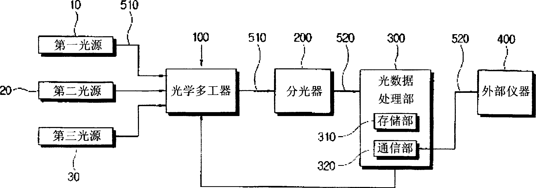
[0025] figure 2 It is a control block diagram for illustrating an optical system provided according to an embodiment of the present invention.

[0026] As shown in the figure, the optical system includes: a plurality of light sources 10 , 20 , 30 ; an optical multiplexer 100 ; a beam splitter 200 ; an optical data processing unit 300 ; and an external device 400 . Each light source 10, 20, 30 and the optical multiplexer 100 and between the optical multiplexer 100 and the optical splitter 200 are connected by an optical fiber 510, and between the optical splitter 200 and the optical data processing unit 300 and the optical data processing unit The communication line 520 such as a universal serial bus (USB) cable is connected between the 300 and the external device 400 .

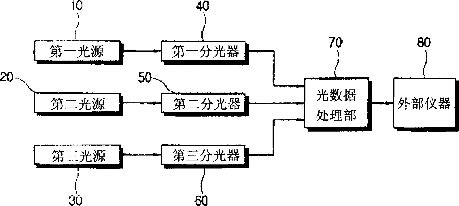
[0027] This embodiment is different from the conventional optical system in that it doe...


PUM


Abstract

The present invention relates to an optical system and control method thereof. The optical system of the invention includes: a plurality of light sources, an optical multiplexer, wherein the optical multiplexer has a plurality of light receive sections receiving the light outputting from the light source, an optical guide part for changing the optical direction of one light receive section from a plurality of light receive sections and guiding to the optical guide part of the light output part; an optical splitter, used for splitting the light from the optical multiplexer and outputting the optical splitting information; an optical data processing part, used for decoding the optical splitting information outputted from the optical splitter and processing. Thereby, an optical multiplexer is provided to select one light from multiterm lights and also a system with simple apparatus and low cost.

Description

technical field [0001] The present invention relates to an optical system including an optical multiplexer and its control method, in particular to an optical system including an optical multiplexer capable of selectively outputting a plurality of input lights and its control method. Background technique [0002] A spectroscope is an optical device for splitting light input from a light source and detecting the intensity of each wavelength of the split light. The user obtains information on the composition or properties of the light source based on the data obtained by the beam splitter. Such beam splitters can also be used in connection with individual chambers used in semiconductor processes etc. for providing all light information generated inside the chamber. [0003] figure 1 It is a control block diagram for explaining an optical system using a conventional beam splitter. As shown in the figure, the optical system includes: a plurality of...

Claims


Application Information

Patent Timeline
Patent Type & Authority Applications(China)
IPC IPC(8): G02B27/10G02B26/08G05D25/00
CPCG01J3/0218G02B6/4214G02B6/422
Inventor 崔命受朴起梁尚兑峻
Owner SAMSUNG ELECTRONICS CO LTD
Why Eureka
Try Eureka