Led drive device

A technology of LED driving and driving current, which is applied in the direction of instruments, electrical components, circuits, etc. It can solve the problems of increased error of current characteristics, inappropriateness, unstable constant current control, etc., achieve high gain and frequency response, and reduce heat generation , good precision effect

Inactive Publication Date: 2007-02-07
HARISON TOSHIBA LIGHTING CORP
View PDF1 Cites 32 Cited by
  • Summary
  • Abstract
  • Description
  • Claims
  • Application Information

AI Technical Summary

Problems solved by technology

[0011] However, in previous Fig. 13, Figure 14 In the LED driving circuit shown, when the power supply V IN When the voltage fluctuation or external noise, and the stray noise entering the current detection resistor part, or the fluctuation in the control loop occurs, the constant current control becomes unstable, so the response speed of the control loop CL3 (frequency characteristics) and technical limitations of too high gain
Therefore, the above-mentioned conventional circuit is most suitable for a mobile phone, etc., where a predetermined constant current flows through the LED 201 to achieve the purpose of sufficient backlighting, but it is used for products such as frequently changing the required constant current value. For example, it is not suitable for products in the field where the dimming function is necessary.
In particular, in the above-mentioned conventional circuit, stable dimming characteristics cannot be obtained in the range of about 10% or less in the dimming rate, and the current characteristic of LED 201 with respect to the dimming rate also increases the error and becomes nonlinear. Further technical improvement is required for the adoption of liquid crystal backlights for car navigation that require linear characteristics down to an extremely low dimming rate of 5% or less

Method used


Image

  • Led drive device
  • Led drive device
  • Led drive device

Examples


Embodiment Construction

[0058] Hereinafter, embodiments of the present invention will be described in detail with reference to the drawings.

[0059] (first embodiment)

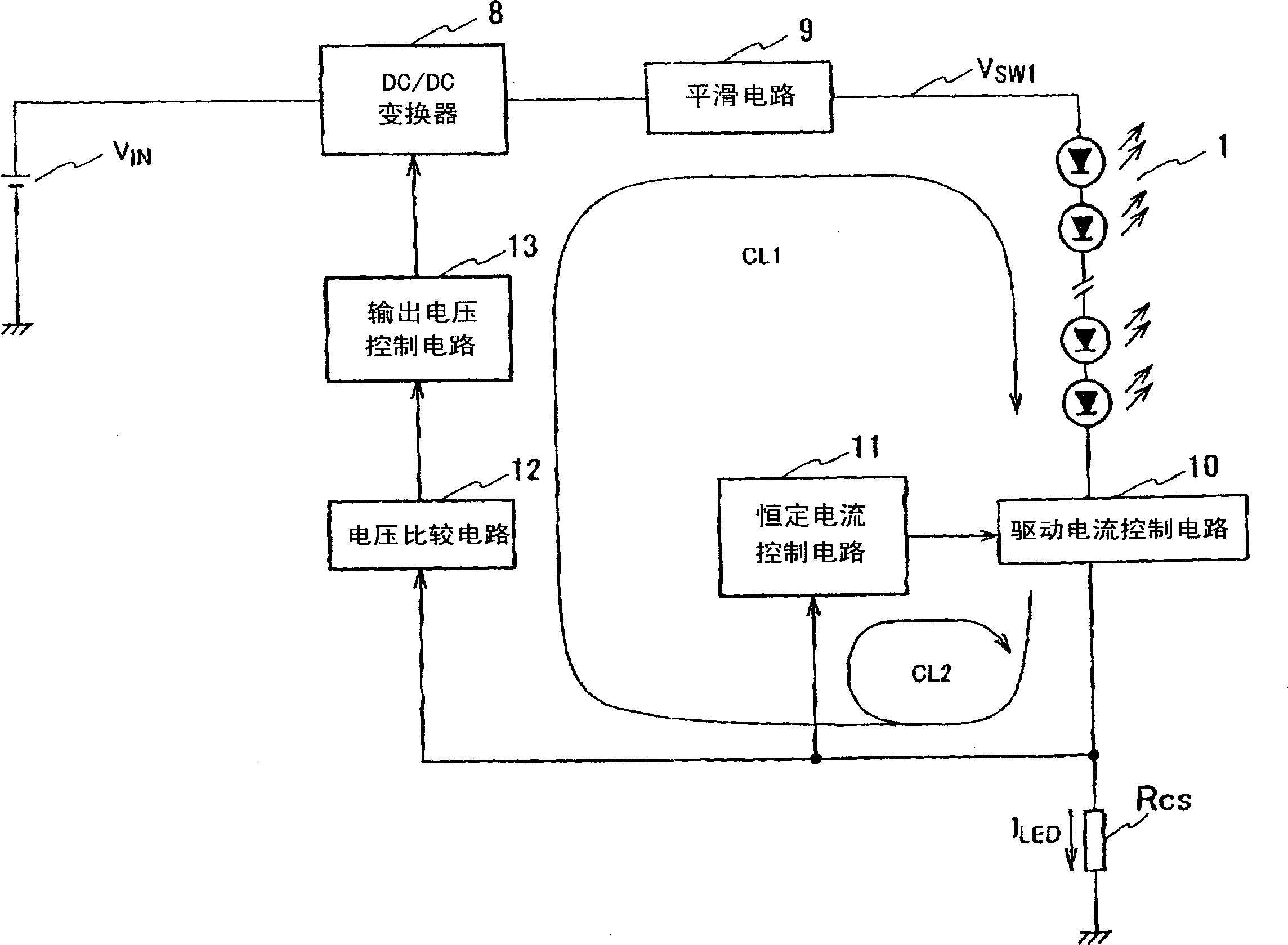
[0060] figure 1 It is a block diagram of the LED driving device according to the first embodiment of the present invention. figure 1 Among them, 1 is a light-emitting diode (LED), 8 is a DC / DC converter, 9 is a smoothing circuit, 10 is a driving current control circuit, 11 is a constant current control circuit, 12 is a voltage comparison circuit, and 13 is an output voltage control circuit.

[0061] Two or more LED1s are connected in series, and the anode side is connected to DC power V from a battery or the like via a smoothing circuit 9 IN A DC / DC converter 8 of a step-down type, a step-up type, or a buck-boost type switch or a circuit breaker type for DC / DC conversion of DC power. The cathode side of LED1 is sequentially connected to a drive current control circuit 10 such as a transistor or FET, and a resistor R for current...


PUM


Abstract

PROBLEM TO BE SOLVED: To provide an LED driving device which can drive an LED by constant current, reduce heat generation of a circuit element group including LEDs by optimizing voltage to be supplied to the LED, and stably light a backlight unit during light controlling. ŽSOLUTION: In the LED driving device, a first negative feedback closed loop CL1 for controlling supply voltage is comprised of a DC / DC convertor 8, an output driving element 10, a voltage comparison circuit 12, and an output voltage control circuit 13, and a second negative feedback closed loop CL2 for controlling constant-current is comprised of an output driving element 10 and a constant-current control circuit 11. The frequency response characteristic of the first negative feedback closed loop CL1 for controlling supply voltage is set to 1 / 20 or less of that of the second negative feedback closed loop CL2 for controlling constant current, so that the first negative feedback closed loop CL1 for controlling supply voltage can be stably operated without spoiling the response of controlling the constant current. Ž

Description

technical field [0001] The invention relates to an LED driving device. Background technique [0002] Mercury-encapsulated cold-cathode fluorescent lamps have been used as a light source in conventional backlights for liquid crystals such as navigation systems. In recent years, in order to reduce the use of mercury, which is a harmful substance, backlights using white or RGB light-emitting diode elements have been used as alternative light sources. The units are compelling and are slowly commoditizing. [0003] Figure 12 A general backlight unit using light emitting diode elements (LEDs) is shown. The backlight unit includes a light guide plate 103 , a back frame 104 and a front frame 106 . The back frame 104 houses the LED mounting substrate 102 . White LEDs 101 are arranged on the LED mounting substrate 102 , and light emitted from the LEDs 101 is deflected by the light guide plate 103 , passes through the optical sheet 105 and the like, and illuminates liquid crystal f...

Claims


Application Information

Patent Timeline
Patent Type & Authority Applications(China)
IPC IPC(8): G09G3/34G09G3/36G09G3/20H01L33/00
Inventor 司马俊明
Owner HARISON TOSHIBA LIGHTING CORP
Why Eureka
Try Eureka