Fuel pre-evaporation and premix perforated pipe

A pre-evaporation and pre-mixing technology, which is applied to engine components, turbine/propulsion fuel delivery systems, charging systems, etc., can solve the problems of slow mixing speed, large size, and unsatisfactory fuel evaporation and pre-mixing effect. The effect of turbulence, small size and simple structure

Inactive Publication Date: 2007-02-14
BEIHANG UNIV
View PDF0 Cites 14 Cited by
  • Summary
  • Abstract
  • Description
  • Claims
  • Application Information

AI Technical Summary

Problems solved by technology

The current fuel pre-evaporation and pre-mixing device mainly relies on turbulent diffusion to mix oil and gas. The mixing speed is slow, the size is large, and the effect of fuel evaporation and pre-mixing is not ideal.

Method used


Image

  • Fuel pre-evaporation and premix perforated pipe
  • Fuel pre-evaporation and premix perforated pipe
  • Fuel pre-evaporation and premix perforated pipe

Examples


Embodiment Construction

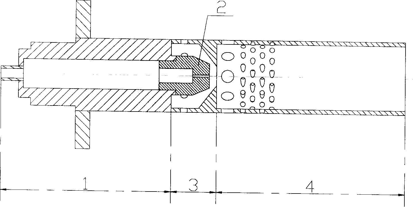
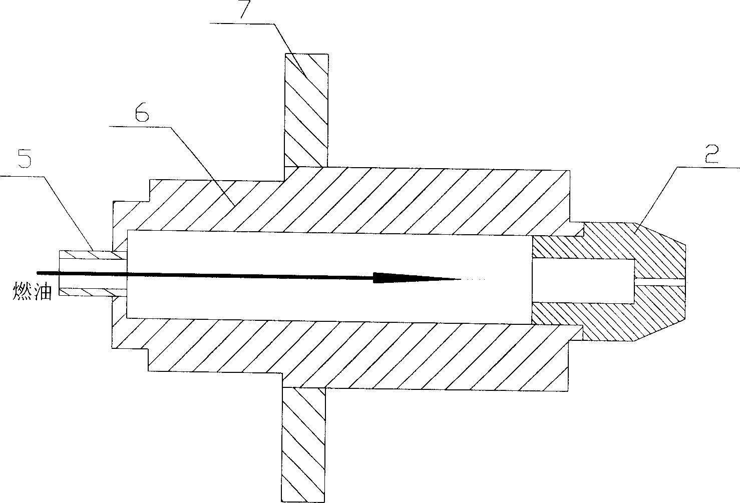
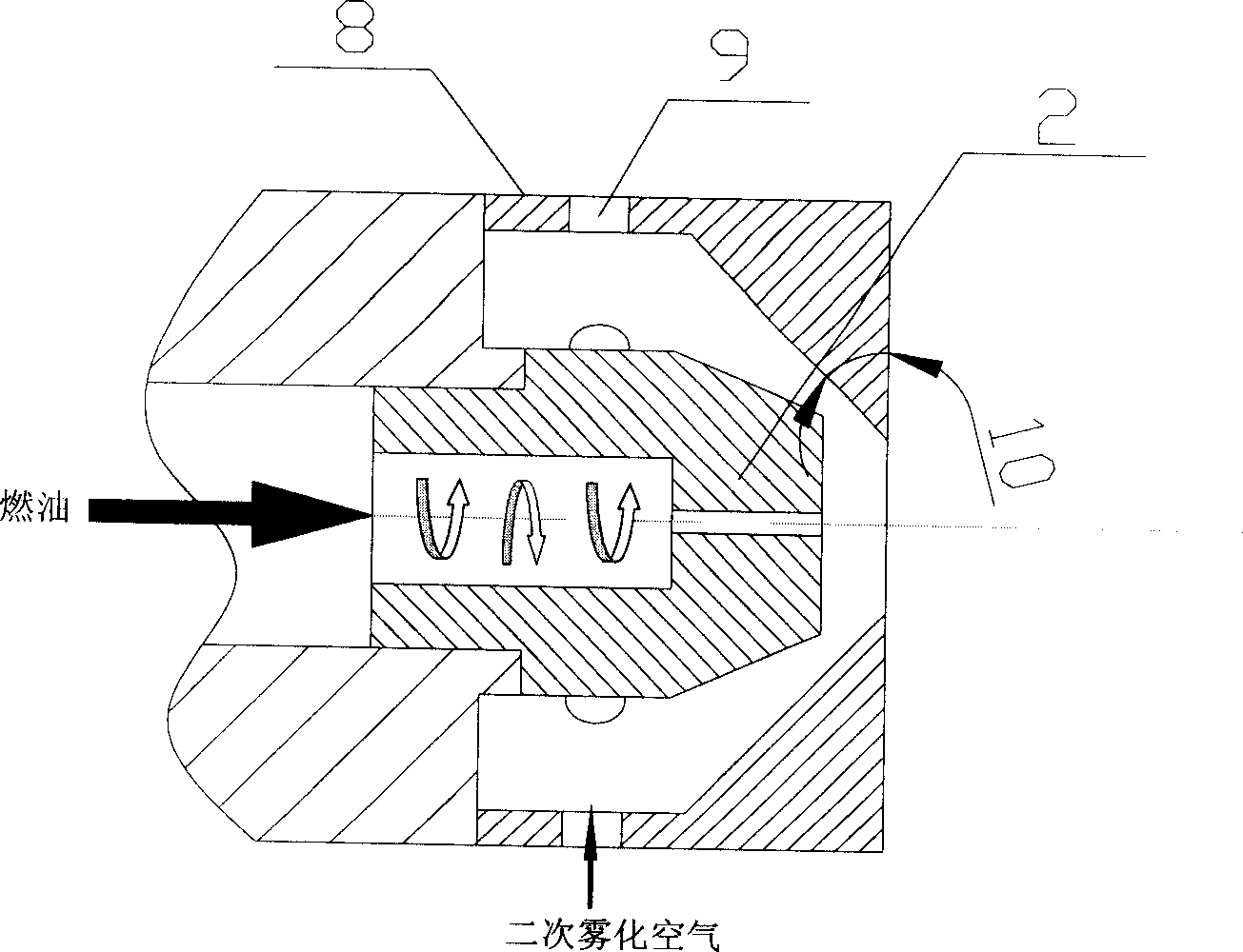
[0023] Such as figure 1 , 2 , 3, 4, the present invention consists of an oil supply part 1, a nozzle section 3 and a mixing section 3. The fuel supply part 1 includes a fuel inlet 5 and a connecting channel 6, and the connecting channel 6 is fixedly connected to external equipment through a flange 7; the outlet of the connecting channel 6 is connected to the fuel nozzle 2 of the nozzle section 3, wherein the fuel nozzle 2 adopts a centrifugal nozzle, and the There are 6-12 straight holes 9 with a diameter of 2.2 to 3.2 mm on the pipe wall 8 of the nozzle section 3, the outlet 10 of the nozzle section 3 is in a contracted shape, and a row of 4 to 10 holes is punched on the pipe wall 11 of the mixing section 4. a straight hole with a diameter of 3.0 to 5.4mm and 50 to 100 4-8 rows of oblique holes 13 with a diameter of 2mm, wherein the angle of the oblique holes 13 is 25° to 50°.

[0024] Table 1 shows the specific dimensions in the above figures

[0025] specific ...


PUM


Abstract

A preevaporating and premixing multihole tube of fuel oil is unit for preparing fuel oil of combustion chamber on gas turbine, which consists of oil supply unit, nozzle section and mixing section. It is featured as drilling straight holes on tube wall of nozzle section, setting outlet of nozzle section to be contraction form and drilling straight holes and slope holes on the wall of mixing section.

Description

technical field [0001] The invention relates to a novel fuel oil preparation device for a low-pollution gas turbine combustion chamber, in particular to a fuel pre-evaporation pre-mixing tube with holes. Background technique [0002] The fuel pre-evaporation and pre-mixing porous pipe involved in the present invention is derived from the development of low-pollution combustion technology. In order to fully control the pollution emissions of the modern gas turbine industry and civil aircraft engines, new low-pollution combustion technologies are required. With the research on low-pollution combustion technology at home and abroad, a variety of technical solutions have been gradually developed, including staged combustion chamber technology, Lean Premixed Prevaporized Combustor (LPP for short), catalytic combustion technology and variable geometry combustion room etc. However, the technology with the greatest potential to reduce pollution emissions is lean pre-evaporative pr...

Claims


Application Information

Patent Timeline
Patent Type & Authority Applications(China)
IPC IPC(8): F02C7/22
Inventor 林宇震朱菁许全宏刘高恩
Owner BEIHANG UNIV
Why Eureka
Try Eureka