Dc solid-state relay

A solid-state relay and circuit technology, applied in electrical components, electronic switches, pulse technology, etc., can solve the problems of large loss of control circuits, drift of electrical parameters, and increase of output current test resistance, achieving good on-resistance characteristics and reliable design. High performance and improved reliability

Active Publication Date: 2007-02-14
BYD CO LTD
View PDF2 Cites 14 Cited by
  • Summary
  • Abstract
  • Description
  • Claims
  • Application Information

AI Technical Summary

Problems solved by technology

Its shortcoming is that it has no overcurrent protection, and it often causes damage to the internal circuit of the solid state relay when the instantaneous large current or load short circuit fault occurs
[0004] As another example, the Chinese patent application number is 94226636, the publication date is December 14, 1994, and the patent name is "a DC solid state relay with overcurrent protection", which discloses a solid state relay, which realizes overcurrent protection Function, but its disadvantage is that it uses optical isolation devices, the switch circuit uses transistors, and needs to increase the output current test resistance, resulting in the following shortcomings:
[0005] 1. Using opto-isolators and transistors, the reliability of these two devices is not high, and the electrical parameters drift, resulting in a decrease in the reliability of the entire product
[0006] 2. Using a transistor to drive the switching tube, the loss of the control circuit is large, especially when the input circuit has an input, the switching tube does not work, and when the input circuit has no input, the switching tube works, and the entire output circuit loses a lot;
[0007] 3. Transistors are used as switching tubes, and the switching circuit cannot achieve high power and high withstand voltage, and the loss is large;
[0008] 4. The output current test resistor is used in the overcurrent protection, which is easy to generate heat. In addition to the energy loss of the switching circuit, the increased sampling resistor also consumes energy, and the price of the sampling resistor is relatively high.

Method used


Image

  • Dc solid-state relay
  • Dc solid-state relay
  • Dc solid-state relay

Examples


Embodiment Construction

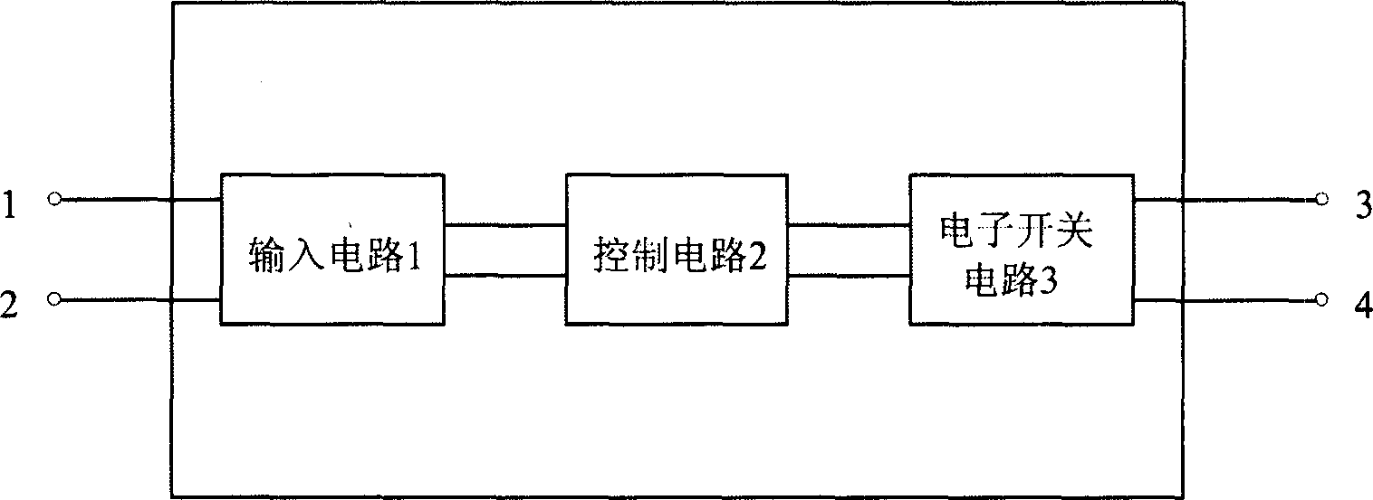
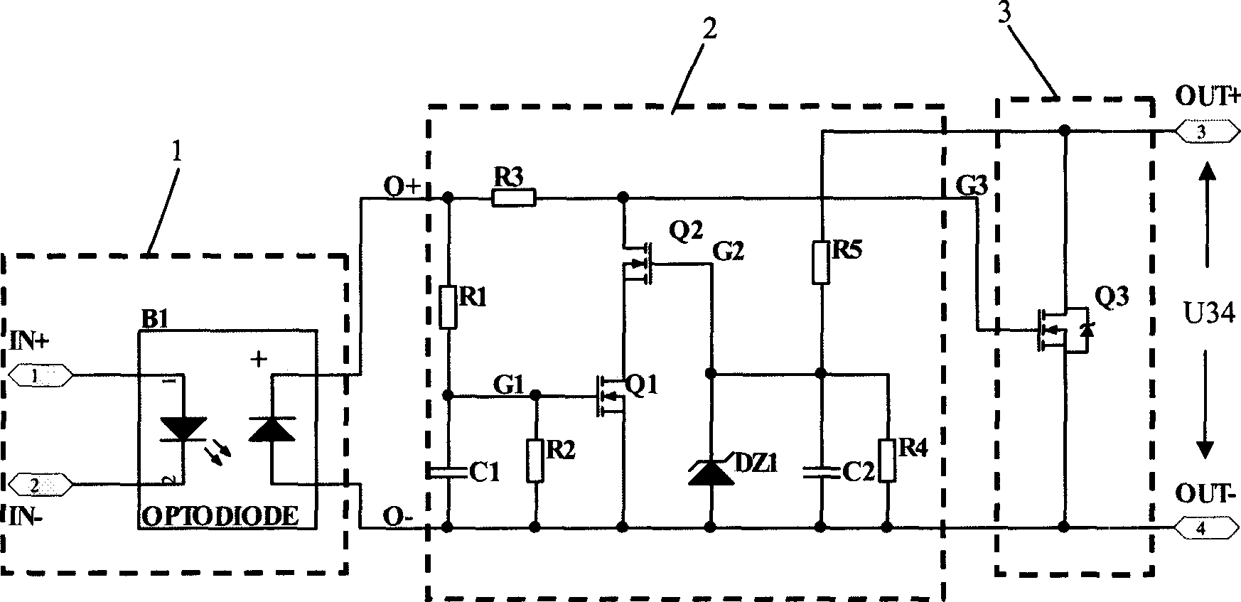
[0023] Such as figure 1 As shown, the DC solid state relay includes an input circuit 1, a control circuit 2 and an electronic switch circuit 3 connected in sequence, the input circuit 1 is used as the input terminal of the relay, and the first and second output terminals of the electronic switch circuit 3 are used as the output terminals of the relay. The electronic switch circuit 3 can be turned on and off according to the current at the input end, so that the external circuit controlled by the relay is turned on or off. Since the photodiode is used as the isolation between input and output in the input circuit, the photodiode has only two input terminals and two output terminals, and there is no need to design an additional secondary side bias voltage terminal, so the DC solid state relay in this embodiment has only two input and two outputs.

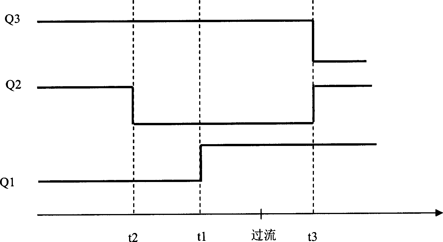
[0024] Please refer to figure 2 , 3 , 4. The circuit structure and working mechanism of this embodiment will be described in det...


PUM


Abstract

This invention discloses a DC solid state relay including an input circuit and an electronic switch circuit responding to the output signals of the input circuit and executing switch operations, in which, the input circuit includes a photoelectric diode, the input of which is connected with exterior circuits, the positive and negative ends are coupled to the electronic switch circuit.

Description

【Technical field】 [0001] The invention relates to a relay, in particular to a DC solid-state relay which isolates and switches through semiconductors. 【Background technique】 [0002] With the development of modern electronic technology, for isolated drive and isolated switching circuit occasions, the traditional single mechanical relay has been developed to the current situation where photoelectric isolated solid state relays are widely used; compared with traditional mechanical relays, photoelectric relays have obvious advantages: volume Small capacity, high switching voltage, strong non-contact shock resistance, so it can be widely used in harsh conditions such as industry and transportation. [0003] For example, the Chinese patent application number is 90102510, the publication date is June 19, 1991, and the patent name is "high-power high-voltage DC solid-state relay" which discloses a solid-state relay whose switching circuit adopts a MOS tube. Realized high power and...

Claims


Application Information

Patent Timeline
Patent Type & Authority Applications(China)
IPC IPC(8): H03K17/785
Inventor 杨海珊
Owner BYD CO LTD
Why Eureka
Try Eureka