Infrared gas analyzer

A gas analyzer, infrared technology, applied in the direction of analyzing materials, material thermal analysis, instruments, etc., can solve the problems of requiring assembly steps, increasing the number of assembly parts, combining complex assembly steps, etc., and achieving the effect of good dimensional accuracy

Inactive Publication Date: 2007-02-28
YOKOGAWA ELECTRIC CORP
View PDF2 Cites 9 Cited by
  • Summary
  • Abstract
  • Description
  • Claims
  • Application Information

AI Technical Summary

Problems solved by technology

[0032] However, such devices contain flow problems regarding mounting and sealing characteristics:
[0035] lead to complex assembly steps (actually bonding steps)
[0036] (3) Therefore, the number of assembly parts increases, and an assembly step is required, causing an increase in cost

Method used


Image

  • Infrared gas analyzer
  • Infrared gas analyzer
  • Infrared gas analyzer

Examples


Embodiment Construction

[0077] The present invention will be discussed in detail with reference to the accompanying drawings.

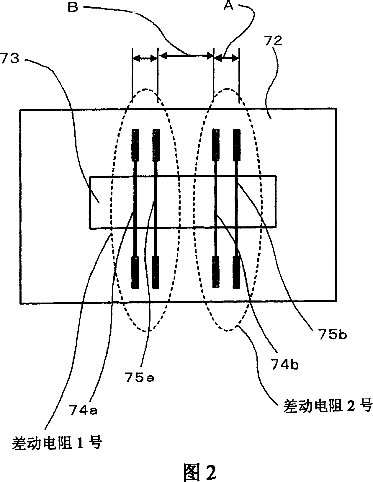
[0078] Fig. 1 is an illustration of the main part configuration of an embodiment of the present invention, and Fig. 2 is

[0079] A detailed illustration of the main parts in Figure 1, where two pairs of heating resistors are used.

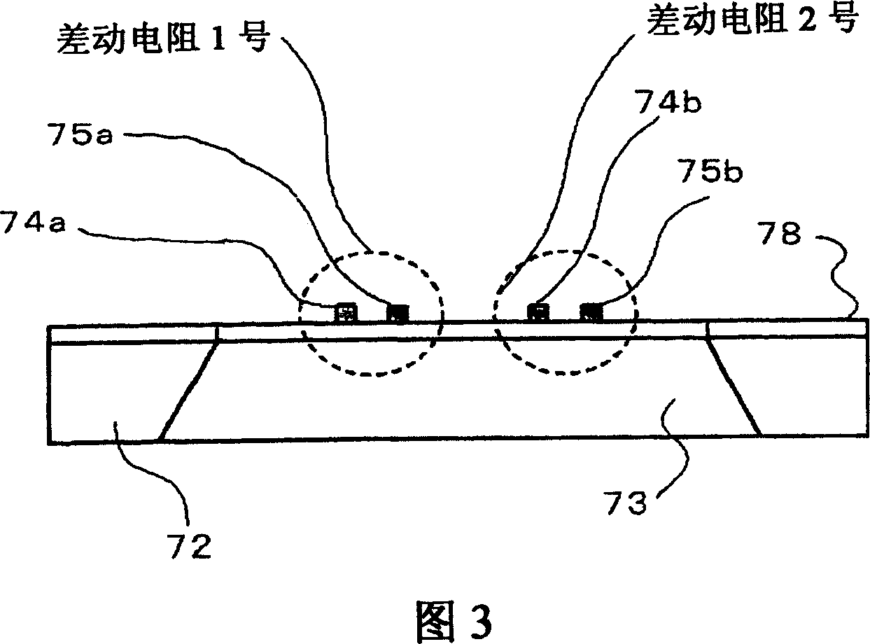
[0080] Fig. 3 is a side view of Fig. 2, and Fig. 4 is a diagram showing a usage example of Fig. 2,

[0081] And FIG. 5 is an operation diagram of FIG. 2 . In Figures 1 to 5 those with respect to Figures 8 and 11 and

[0082] The same parts as previously described are denoted by the same reference numerals.

[0083] Only the differences from the relevant process examples in Figures 8 and 11 will be discussed below:

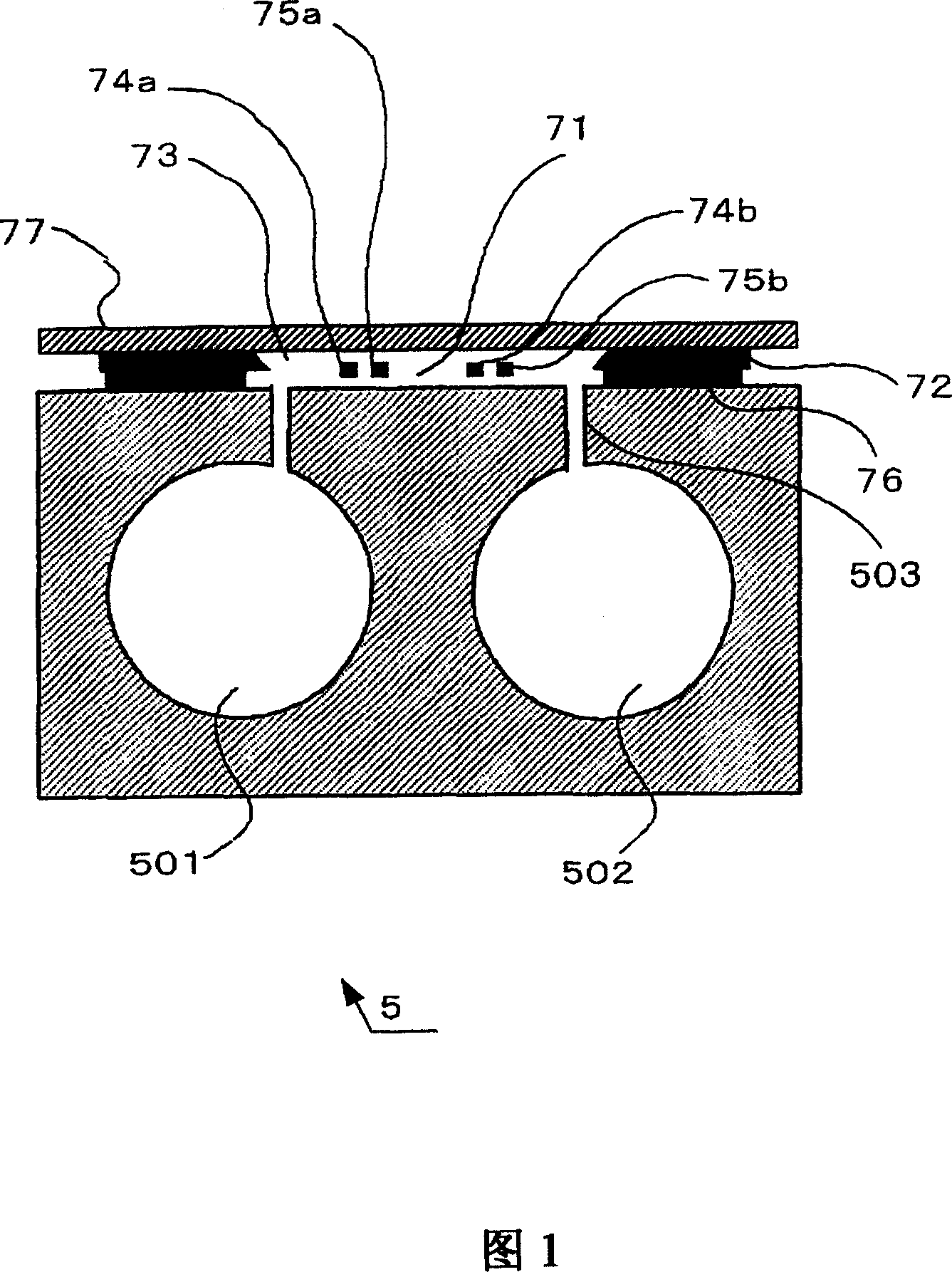
[0084] The flow channel 71 is provided parallel to one side of the detector 5 .

[0085] The base 72 has a flat plate placed parallel to the airflow direction of the airflow channel 71 .

[0086] Holes 73 are made in the flat p...


PUM


Abstract

An infrared gas analyzer includes a flow sensor placed in a gas flow channel in a state in which two heating resistors are kept with a given spacing. The infrared gas analyzer further includes a substrate having a flat plane placed in parallel with the gas flow direction of the gas flow channel and a hole made in the flat plane of the substrate. The gas flow channel is provided in parallel with one face of a detector. The two heating resistors placed with a predetermined spacing on the substrate across the hole orthogonally to the gas flow direction.

Description

technical field [0001] The invention relates to an infrared gas analysis using infrared light to measure gas concentration [0002] The utility model relates to an infrared gas analyzer which can be easily assembled and can reduce costs. Background technique [0003] Technical literature related to infrared gas analyzers and flow sensors used with them [0004] as follows: [0005] [Non-Patent Document 1] General Specification, "IR400 Infrared Gas Analyzer", May 2002, first edition, p5, issued by Yokogawa Electric Co., Ltd. [0006] [Patent Document 1] Unexamined Japanese Patent Publication No. 2002-131230. [0007] [Patent Document 2] Unexamined Japanese Patent Publication No. 2002-081982. [0008] Fig. 8 is an illustration of the structure of a related art example commonly used so far. FIG. 9 is a conceptual illustration of FIG. 8 . FIG. 10 is a diagram of the bridge circuit in FIG. 8 . FIG. 11 is an illustration of the structure of main parts in FIG. 8 . FIG. 12 i...

Claims


Application Information

Patent Timeline
Patent Type & Authority Applications(China)
IPC IPC(8): G01N21/00G01N25/00H05B3/10H05K3/00H05K3/06
CPCG01N21/37G01F15/14G01F1/6842G01F1/6845G01F1/692
Inventor 山岸秀章松尾纯一南光智昭松村茂
Owner YOKOGAWA ELECTRIC CORP
Why Eureka
Try Eureka