Household appliance controlling system

A technology for control systems and household appliances, applied in the field of automation, can solve the problems of large power line noise, easy signal interference, complicated operation, etc., and achieve the effect of large-scale control and simple and clear control process.

Inactive Publication Date: 2007-02-28
潘卫文
View PDF0 Cites 10 Cited by
  • Summary
  • Abstract
  • Description
  • Claims
  • Application Information

AI Technical Summary

Problems solved by technology

The disadvantage of this system is that it is complex to operate
[0006] The power carrier technology invented in the 1970s has been used in the field of home intelligence. The principle is to use the power line as the carrier to transmit the control signal. The advantage of this method is that no additional wiring is required and the control is relatively simple. The disadvantage is that the power line The noise is large, the signal is easily interfered, and the reliability of the system cannot reach 100%.
Therefore, this technology has not been widely promoted until now.

Method used


Image

  • Household appliance controlling system
  • Household appliance controlling system
  • Household appliance controlling system

Examples


no. 1 example

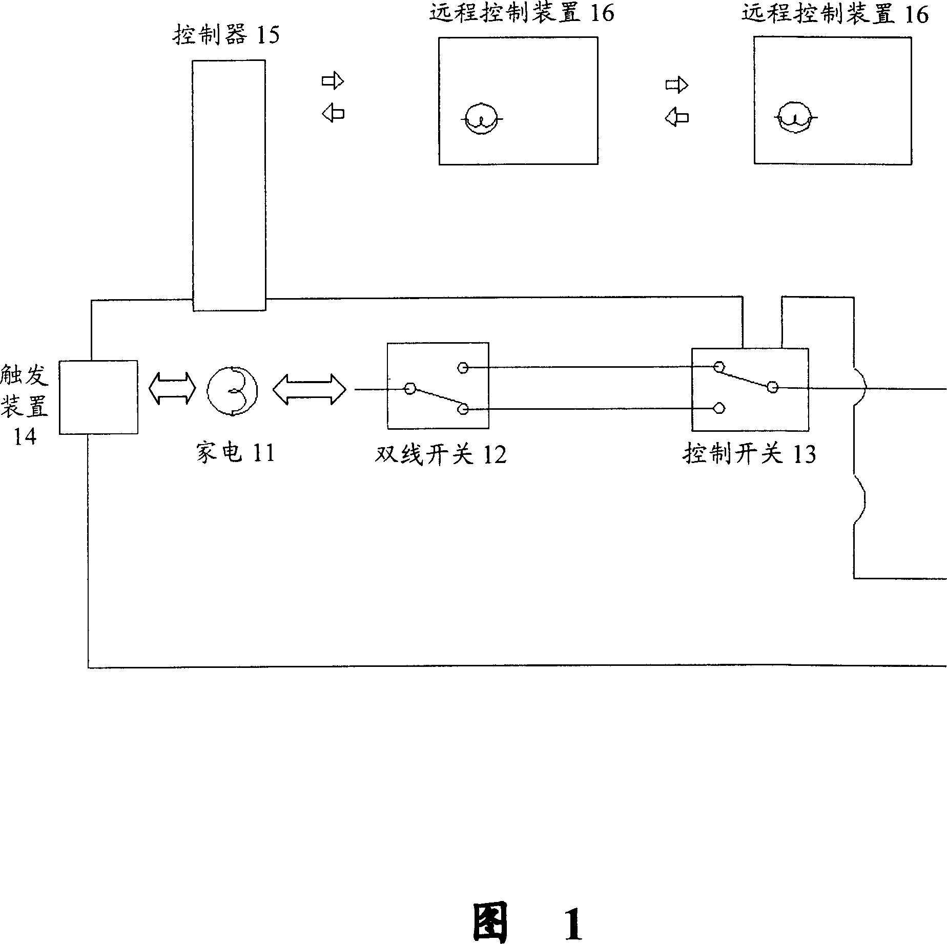
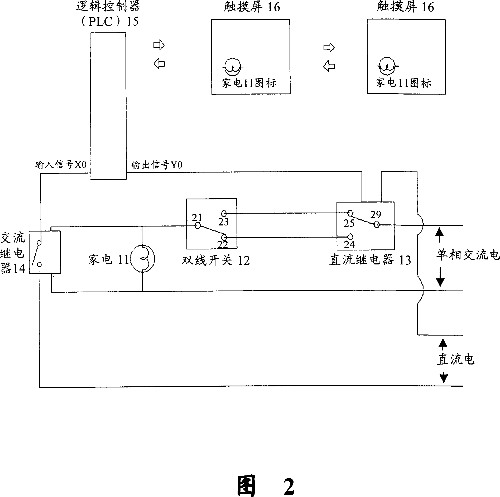
[0044] First refer to Figure 2. In Figure 2, an AC relay is used as the trigger device, a logic controller is used as the controller, and a DC relay is used as the control switch. The remote control device is realized by multiple touch screens set in master-slave mode. It includes the following structures:

[0045] An appliance 11 is connected to a two-wire switch 12, and the two-wire switch 12 is connected to a control switch 13, and further includes:

[0046] An AC relay 14, connected in parallel at both ends of the home appliance 11;

[0047] A logic controller (PLC) 15, the input end is connected with the AC relay 14, and the output end is connected with the DC relay 13, and the logic controller (PLC) 15 controls the household appliances 11; the logic controller (PLC) is used as the control logic of the controller Refer to Figure 8 for the schematic diagram.

[0048] One or several remote control devices 16 are communicatively connected to a logic controller (PLC) 15, th...

no. 2 example

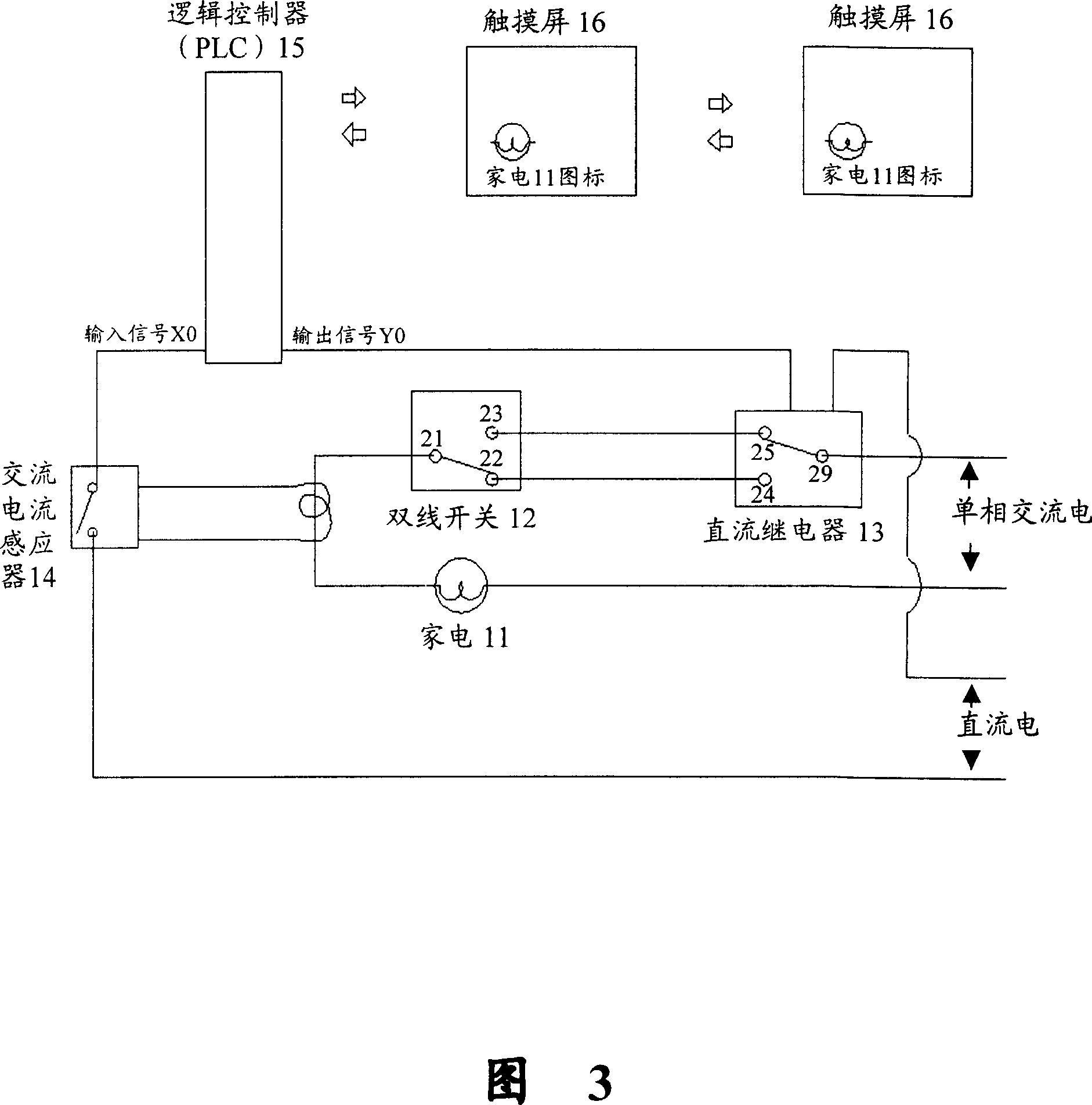
[0070] Fig. 3 is a control circuit diagram of a household appliance control system according to another embodiment of the present invention, wherein an AC current sensor is used as a trigger device, a logic controller is used as a controller, a DC relay is used as a control switch, and the remote control device uses multiple One is set to master-slave mode touch screen implementation. It includes the following structures:

[0071] An appliance 11 is connected to a two-wire switch 12, and the two-wire switch 12 is connected to a control switch 13, and further includes:

[0072] An AC current sensor 14 is connected in parallel at both ends of the household appliance 11;

[0073] A logic controller (PLC) 15, the input end is connected with the AC current sensor 14, the output end is connected with the DC relay 13, the logic controller (PLC) 15 controls the household appliances 11; the logic controller (PLC) is used as the controller Refer to Figure 8 for the schematic diagram o...


PUM


Abstract

The invention relates to a family appliance control system, which comprises: a family appliance connected to a dual-wire switch; a dual-wire switch connected to a control switch, a trigger device parallel connected to two ends of family appliance; a controller whose input is connected to the trigger device and output is connected to the control switch to control the family appliance; one or several remote controllers connected to the controller while the character of family appliance is displayed on the remote controller; the remote controller via the controller can control family appliance. With said invention, user can control family appliance traditionally or remotely. The invention can make the controlled object feedback itself state in time. Said system can directly and simply control family appliance.

Description

technical background [0001] The invention relates to the technical field of automation, and more specifically relates to a control system for household appliances. Background technique [0002] At present, in terms of intelligent control of household appliances, the control of home appliances mainly includes infrared control, radio frequency (RF) control, and control through keyboard or voice system. [0003] Infrared control is that the remote control sends out infrared remote control signals, and the infrared receiver performs actions after receiving relevant signals, such as ordinary air conditioner remote control; or the remote control directly controls the switch equipped with the infrared receiver, usually this switch is a two-wire Switch, you can choose a mechanical switch, or you can choose an infrared remote control. The disadvantage of this control method is that the control range is small, and there must be no barrier between the receiver and the transmitter, so ...

Claims


Application Information

Patent Timeline
Patent Type & Authority Applications(China)
IPC IPC(8): G05B19/05G05B15/02H04M11/00G06F3/03
Inventor 潘卫文
Owner 潘卫文
Why Eureka
Try Eureka