Positive-negative voltage conversion circuit

A technology for converting circuits and positive and negative voltages, which is applied in the direction of output power conversion devices, electrical components, and adjustment of electrical variables. Ideal adjustment rate, large load current and simple circuit

Inactive Publication Date: 2007-03-07
STATE GRID TIANJIN ELECTRIC POWER
View PDF0 Cites 10 Cited by
  • Summary
  • Abstract
  • Description
  • Claims
  • Application Information

AI Technical Summary

Problems solved by technology

[0004] 1. Realized by using smart IC chips from MAXIM and other companies. This solution is mainly used in low-power systems with low current (1A), and the cost is relatively high
[0005] 2. It is realized by Buck-Boost circuit designed by discrete components. The circuit design of this scheme is complex and bulky
[0013] The disadvantages of the above circuit are as follows: The load capacity of the circuit is poor. When the output current is greater than 0.5A, the output ripple is greater than 200mV, the load regulation rate is greater than ±2%, and the output voltage cannot meet the requirements.

Method used


Image

  • Positive-negative voltage conversion circuit
  • Positive-negative voltage conversion circuit
  • Positive-negative voltage conversion circuit

Examples


Embodiment Construction

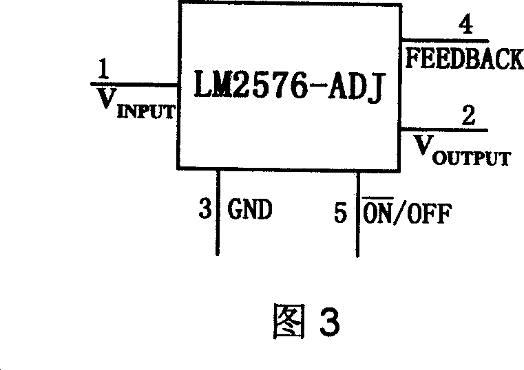
[0033] Figure 3 is a schematic diagram of the pin description of the chip LM2576, as shown in Figure 3:

[0034] 1 pin (V INPUT ): voltage input terminal, the input voltage range is 4V ~ 40V;

[0035] 2 feet (V OUTPUT ): voltage output terminal, output adjustable voltage range 1.23V ~ 35V;

[0036] 3 feet (GND): input voltage negative terminal;

[0037] Pin 4 (FEEDBACK): output voltage feedback terminal;

[0038] Pin 5: (ON / OFF): output voltage control terminal.

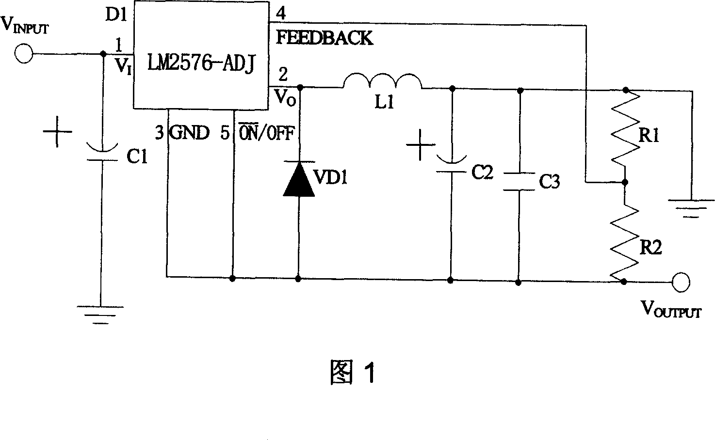
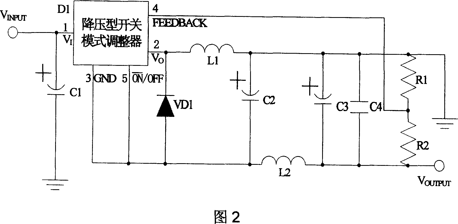
[0039] The present invention is applicable to devices (products of MICREL, ON Semiconductor, National Semiconductor, etc.) that use a step-down switch mode regulator to realize positive and negative voltage conversion.

[0040] The working principle of the present invention is as follows:

[0041] (1) When the built-in switch of the step-down switching mode regulator chip is turned on, the input voltage charges the inductor L1 after input filtering, the current flows through the inductor coil L1, and L1 stores ...


PUM


Abstract

This invention provides one positive and negative voltage conversion circuit, which comprises the following parts: one dropping switch mode adjustor; electrolyte capacitor, diode, output memory induction, electrolyte capacity, high frequency filter capacitor, feedback resistance network, output filter induction and electrolyte capacity. This invention adopts filter induction to eliminate voltage beam wave and load ability resulted by Buck-Boost circuit and put filter induction on negative end.

Description

technical field [0001] The invention relates to a DC positive and negative voltage conversion circuit, more specifically a circuit for realizing relatively large power positive and negative voltage conversion. Background technique [0002] With the rapid development of modern electronic technology and high-speed ultra-large-scale integrated circuits, more and more electronic systems require positive and negative voltages to work normally. Circuit design requires a negative polarity voltage power supply with a large output current (>1A). Also getting bigger and bigger. However, there are few technical solutions that can provide positive and negative voltage conversion with strong practicability and simple circuit. [0003] The existing technical solutions for negative voltage output circuits mainly include: [0004] 1. Realized by using smart IC chips from companies such as MAXIM. This solution is mainly used in low-power systems with small currents (<1A), but cannot ...

Claims


Application Information

Patent Timeline
Patent Type & Authority Applications(China)
IPC IPC(8): H02M3/00
Inventor 许国锋徐波
Owner STATE GRID TIANJIN ELECTRIC POWER
Why Eureka
Try Eureka