Whole circuit temperature-controlling electric heating device

A circuit and electric heating technology, applied in electric heating devices, ohmic resistance heating, electrical components, etc., can solve the problems of harmonic interference of phase-shift temperature control appliances, high failure rate of appliances, and difficulty in temperature control, so as to achieve no harmonic interference. , high safety, no effect of electromagnetic pollution

Active Publication Date: 2010-11-03
李木水
View PDF6 Cites 1 Cited by
  • Summary
  • Abstract
  • Description
  • Claims
  • Application Information

AI Technical Summary

Problems solved by technology

It consists of a heating carrier, a heating element and a controller. The heating element is installed on the heating carrier, and one end of the heating carrier is connected to the contact interface, connected to the contact interface and the controller through a flexible wire, and connected to the mains power supply through the power plug. The controller includes The shortcomings of the shell and the control circuit installed in it are that, firstly, the appliance has many components, many interface contacts, and many connecting cords, which easily leads to high failure rate of the appliance, high repair rate, and high cost. The process is complicated; secondly, there are harmonic interference in the phase-shifting temperature control appliances, which leads to electromagnetic pollution; thirdly, due to the large interface size, it is difficult to realize temperature control in small electric heating appliances

Method used


Image

  • Whole circuit temperature-controlling electric heating device
  • Whole circuit temperature-controlling electric heating device
  • Whole circuit temperature-controlling electric heating device

Examples


Embodiment 1

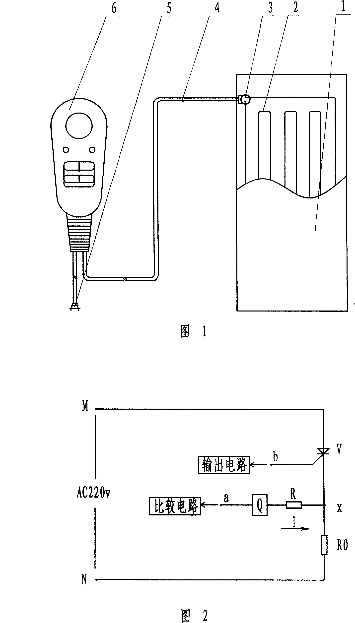
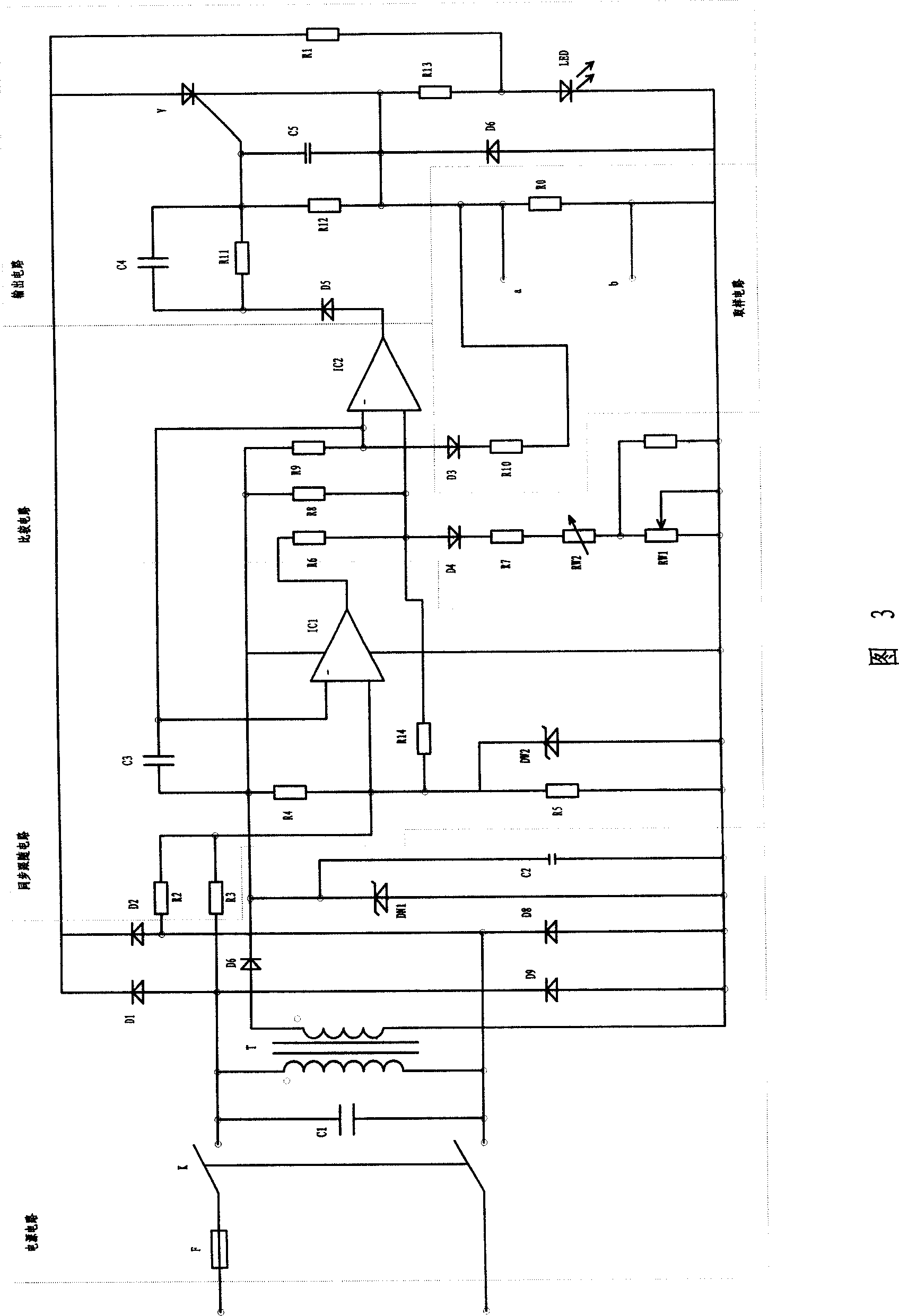
[0029] Embodiment 1, the electrical schematic diagram of the full-wave working power supply, such as image 3 As shown, the power supply circuit is divided into two circuits, one is composed of fuse F, transformer T, diode D6, voltage regulator DW1, and filter capacitor C2, which provides the control circuit with a regulated power supply; the other is composed of diode D1 1 , D2, D8, and D9 are composed of the executive element thyristor V, which is controlled by the control circuit to apply voltage to the heating element RO.

[0030] The synchronous follower circuit is composed of resistors R2, R3, R4, R5, operational amplifier IC1, capacitor C3, and limit regulator DW2. The potential of the negative input terminal of the operational amplifier IC1 is taken from the negative input terminal of the comparison circuit of IC2. R4 and R5 are bias resistors, and R2 and R3 follow the resistors synchronously to provide the input voltage of the positive terminal of IC1, so that the ou...

Embodiment 2

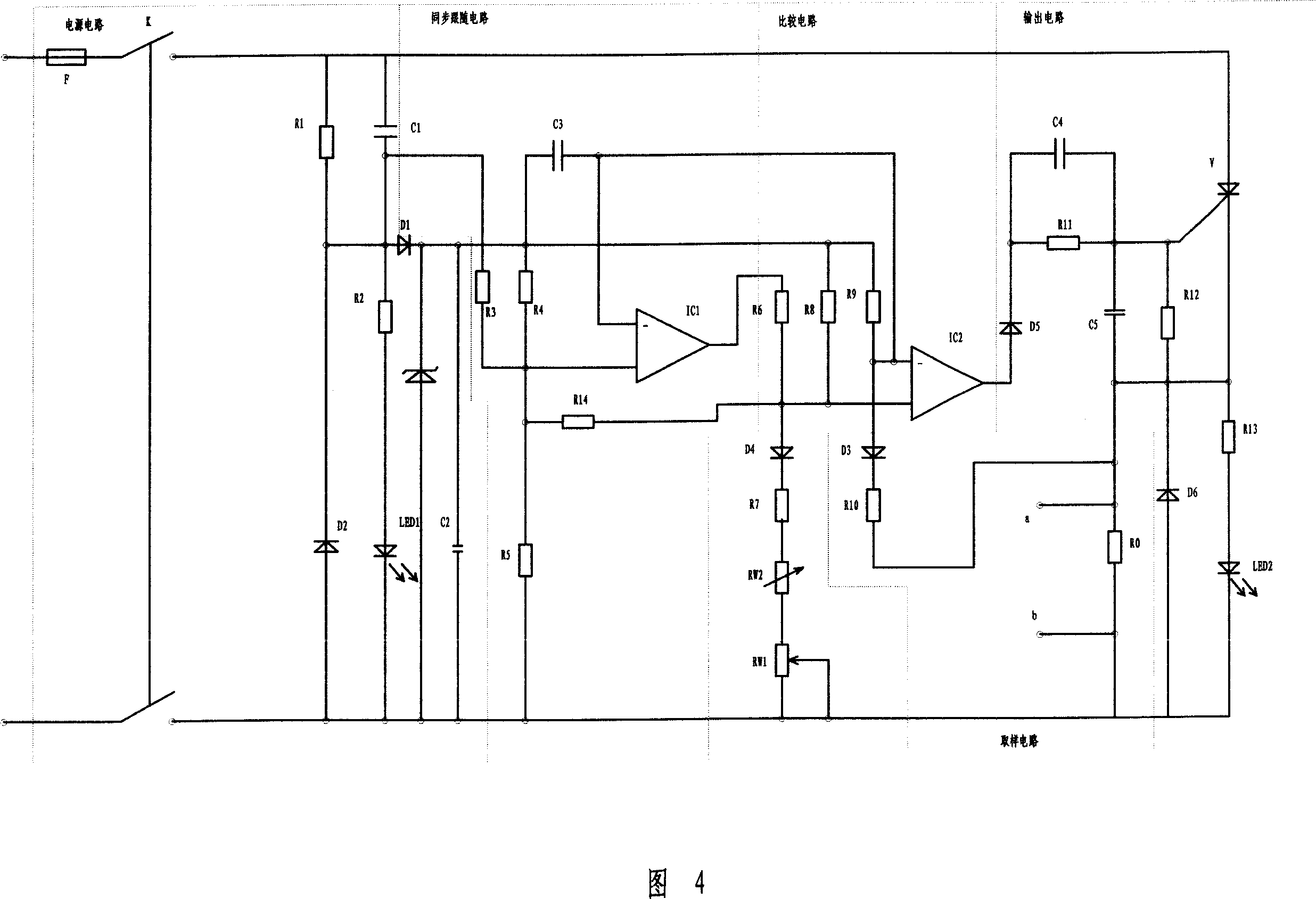
[0033] Embodiment 2, as shown in the figure, is a schematic diagram of the half-wave control circuit. Its principle is the same as that of the full-wave control, except that the control circuit is in the half-wave control state, and the heating element RO is controlled to work when the grid voltage is half-wave. The wave control circuit outputs a low level, the thyristor V is turned off, and the heating element RO does not work all the time.

[0034] In order to prevent the output circuit and output signal of the control circuit from interfering with the sampling circuit and causing the control circuit to get out of control, two methods are adopted. The first is that the output circuit adopts transformer coupling and photoelectric coupling (solid state relay). The output signal of this type of output circuit Without passing through the heating element RO, the sampling circuit will not be disturbed when sampling near the zero point of the grid waveform. The entire control circu...


PUM


Abstract

This invention relates to whole circuit temperature constant heating device, which comprises heating load, heating element and control device, wherein, control device comprises power circuit, synchronous trace circuit, compare circuit, output circuit and sample circuit composed of conductive parts, resistance and heating parts; execution elements controllable cathode one path is connected to the heating element and with other connected to output circuit.

Description

technical field [0001] The invention relates to a temperature control device of an electric heating appliance which generates heat by wires. Background technique [0002] The existing flexible and rigid electric heating appliances that generate heat by wires all use two separate parts, the heating element and the temperature sensing body, in terms of temperature control technology, that is, the sampling of the temperature control signal is caused by the temperature change of the heating element. The resistance value of the temperature body changes and is fed back to the corresponding control circuit to realize the temperature control device. It consists of a heating carrier, a heating element and a controller. The heating element is installed on the heating carrier, and one end of the heating carrier is connected to the contact interface, connected to the contact interface and the controller through a flexible wire, and connected to the mains power supply through the power p...

Claims


Application Information

Patent Timeline
Patent Type & Authority Patents(China)
IPC IPC(8): H05B1/02H05B3/00
Inventor 李木水
Owner 李木水
Why Eureka
Try Eureka