Transmission apparatus

一种传输装置、终端装置的技术,应用在传输系统、选择装置、数字传输系统等方向,能够解决包到达时间间隔变化、处理效率降低、产生抖动等问题,达到消除时隙位置的变动、确保通信质量、稳定通信质量的效果

Inactive Publication Date: 2007-03-14
HITACHI LTD
View PDF0 Cites 9 Cited by
  • Summary
  • Abstract
  • Description
  • Claims
  • Application Information

AI Technical Summary

Problems solved by technology

For this reason, the packet arrival time interval of fixed-band data varies, and jitter occurs
In addition, although the fixed frequency band data is widely used in communication and the communication period is fixed, the frequency band is set in the same method and frequency as the variable frequency band data when calculating the frequency band allocation amount, which may lead to a decrease in processing efficiency
[0011] In packet communication using variable-length data like Ethernet, a certain amount of data cannot be transmitted within a certain period, and jitter cannot be suppressed
Also, jitter cannot be completely suppressed in ATM, and in order to solve this problem, it is necessary to maintain a constant interarrival interval of cells during a fixed communication session

Method used


Image

  • Transmission apparatus
  • Transmission apparatus
  • Transmission apparatus

Examples


Embodiment approach 1

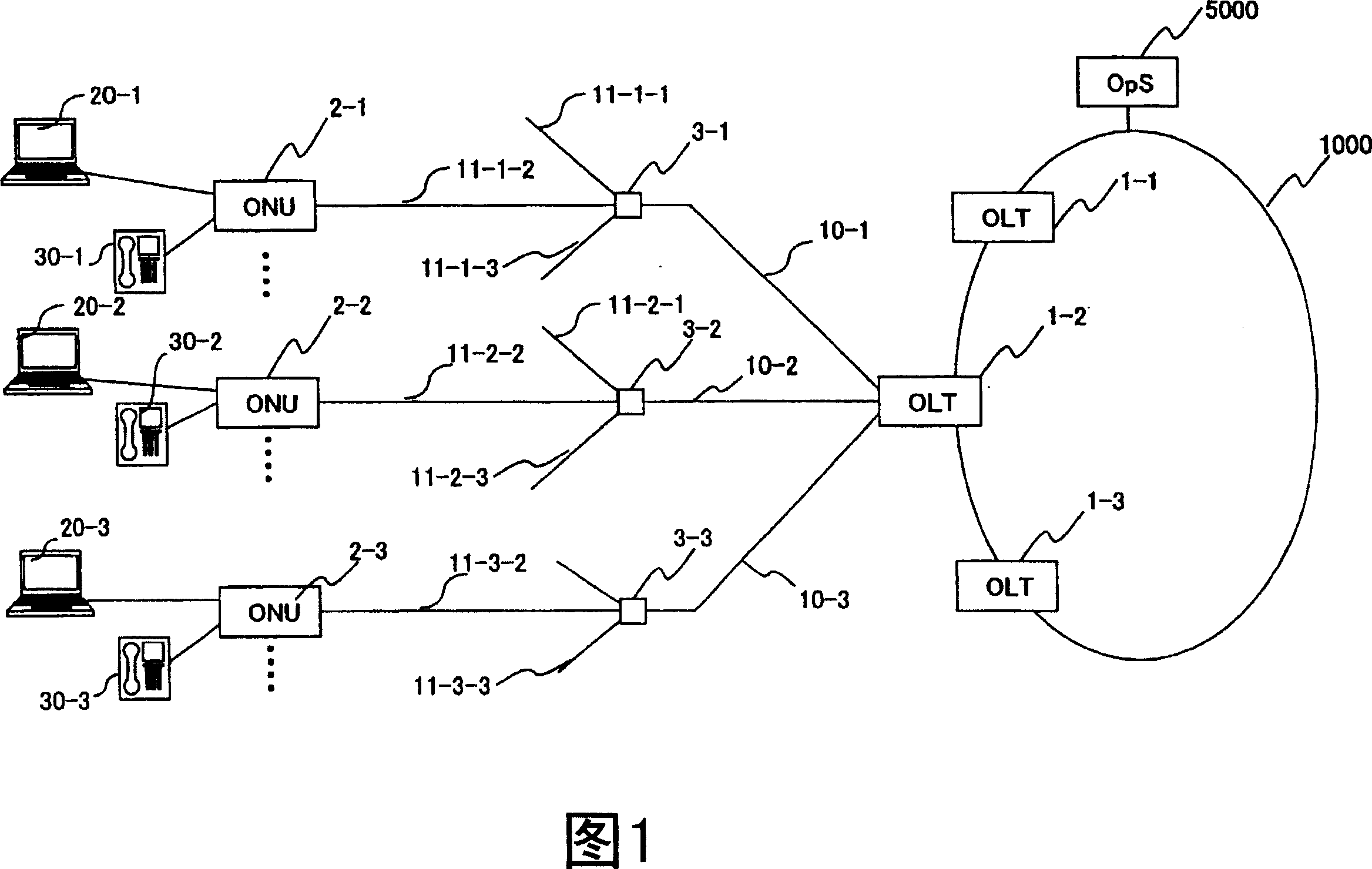
[0036] FIG. 1 is a block diagram showing the configuration of a subscriber terminal network configured using a PON system according to Embodiment 1 of the present invention.

[0037] This network has OLT1-1~1-3, ONU2-1~2-3, optical splitter 3-1~3-3, optical fiber 10-1~10-3 and 11-1~11-3. A plurality of OLTs 1-1 to 1-3 are installed at the edge of the user accommodation network, and each OLT accommodates a plurality of ONUs. OLT1-1~1-3 respectively have multiple PON-IFs (described in the following figure 2), for example, OLT1-2 connects ONU2- 1. Connect ONU2-2 through optical fiber 10-2, optical splitter 3-2, and optical fiber 11-2-2, and connect ONU2-3 through optical fiber 10-3, optical splitter 3-3, and optical fiber 11-3-2.

[0038] The optical splitters 3-1 to 3-3 branch (replicate) the signals sent from the OLT 1-2 through the optical fibers 10-1 to 10-3 to the optical fibers 11-1-1 to 11-1-3 respectively branched on the ONU side , 11-2-1~11-2-3, 11-3-1~11-3-3. And, th...


PUM


Abstract

The invention provides a communication technology wherein a delay is made constant in order to support data communication using a telephone line and wherein real time performance is a requirement. A transmission apparatus for use in fixed bandwidth communications and variable bandwidth communications. The transmission apparatus has a memory unit, which stores information contained in a frame and indicating the amount of data to be transmitted from a terminal device, a computing unit, which calculates a bandwidth amount to be assigned to the terminal device based on the data amount, and a transmission unit, which sends the calculated assigned bandwidth amount to the terminal device. The transmission apparatus is characterized in that the computing unit calculates bandwidth amounts to be assigned to different types of flow of which different transmission qualities are requested according to a priority level that is set to each flow type. The transmission apparatus is also characterized in that bandwidth is controlled by designating, instead of a necessary bandwidth amount, transmission starting timing and transmission ending timing, particularly for fixed bandwidth communication data.

Description

technical field [0001] The present invention relates to a transmission device that divides data into frames or packets for transmission and reception, and particularly relates to a transmission that multiplexes and accommodates connections with multiple terminal devices after physically or logically connecting them. Among the devices, there is a frequency band allocating device that controls the data transmission amount of each terminal device. Specifically, in a subscriber line terminal device that provides a connection line from a user's house, office building, or collective house to a carrier's subscriber line accommodation office, using an optical cable for the access line, using wavelength division multiplexing or time division The multiplexing method multiplexes data from user terminals, and dynamically controls line terminal devices that allocate frequency bands according to data transmission requests from users. Background technique [0002] The transmission capacit...

Claims


Application Information

Patent Timeline
Patent Type & Authority Applications(China)
IPC IPC(8): H04L5/26H04J4/00H04Q11/00H04L12/44H04L12/801H04L12/851H04L12/911
CPCH04L47/365H04L47/30H04L47/2433H04L47/10H04L12/5695H04L47/263H04L47/805H04L47/788H04L47/15H04L47/70
Inventor 水谷昌彦芦贤浩高濑诚由坂本健一岩村笃加沢彻坂本宪弘
Owner HITACHI LTD
Why Eureka
Try Eureka