Detection method with blood pressure monitor and korotkoff sound delaying and pulse wave conducting time signal generator
A technology of conduction time and detection method, applied in the direction of cardiac catheterization, etc., can solve the problems that cannot meet the mutual coordination of blood pressure monitors
- Summary
- Abstract
- Description
- Claims
- Application Information
AI Technical Summary
Problems solved by technology
Method used
Image
Examples
Embodiment 1
[0039] This example is a device that adopts the method of the present invention—a signal generator of Korotkoff sound delay time and pulse wave transit time.
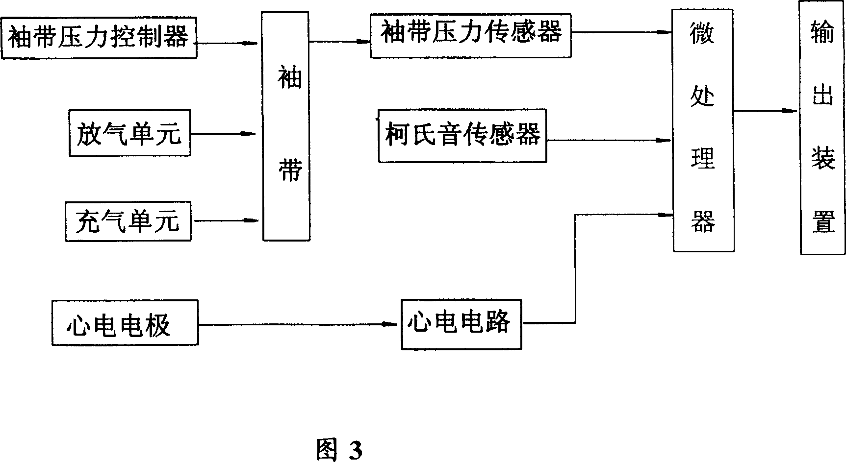
[0040] The structure of this device is shown in Figure 4: It is equipped with a central control microcontroller, a memory used to store data including ECG, pulse wave, respiration, and Korotkoff sound waveform. The microcontroller is connected with the digital / analog converter and signal conditioning circuit through a digital / analog converter and a signal conditioning circuit. Human body analog signal output terminal connection;
[0041] The structure of the cuff pulse wave pressure signal generating device in this example is: equipped with a gas storage device, its input end is connected with an inflatable motor controlled by a single-chip microcomputer, and the output end is connected with the cuff through a gas circuit switch controlled by the single-chip microcomputer.
[0042] The method of generating physiological sig...
Embodiment 2
[0047] This example is several specific implementation working modes of the method of the present invention.
[0048] In view of the several main detection processes disclosed in ZL200510071813.0 and PCT / CN2005 / 001210 patent applications that use Korotkoff sound delay time and pulse wave transit time to monitor blood pressure, this example sets several working modes that adapt to their different detection processes. The following describes them one by one:
[0049] 1. This working mode is aimed at the following detection process of the blood pressure monitor: After the blood pressure monitor obtains the PWTT coefficients a and b in the calculation formula, it calculates the blood pressure value BP by measuring the PWTT.
[0050] 1-1. Brief description of the detection process of blood pressure monitor:
[0051] According to the relationship between PWTT and arterial blood pressure BP:
[0052] BP=a+b*PWTT ……(A)
[0053] Where BP is arterial blood pressure, PWTT is pulse wave trans...
Embodiment 3
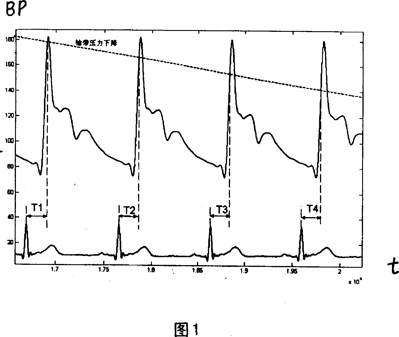
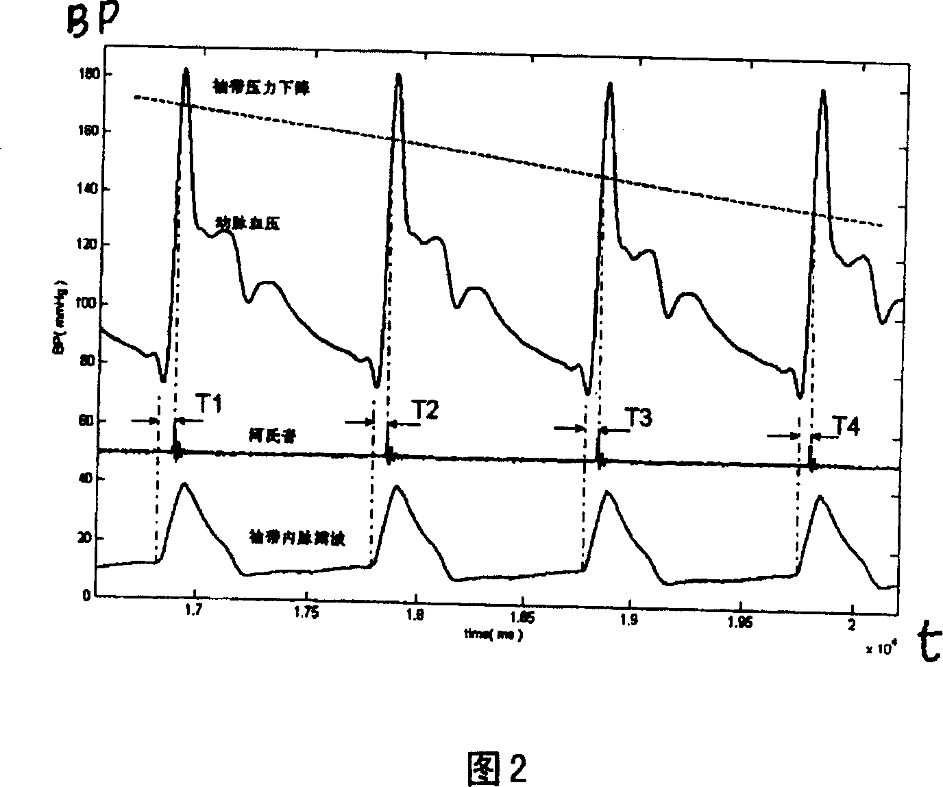
[0089] The difference from Embodiment 2 is that in the 2-2 working mode, Embodiment 2 expresses the Korotkoff sound delay time T by the time interval from the start point of the cuff pulse wave to the Korotkoff sound arrival time. K Signal, in this example, the time interval between the peak of the ECG R wave and the arrival of the Korotkoff sound is expressed as the Korotkoff sound delay time T K The signal (see Figure 1) starts timing from the peak value of the ECG R wave. When the Korotkoff sound delay time of the set blood pressure is reached, the starting point of the Korotkoff sound signal and subsequent waveforms are output.
[0090] In this example, the relationship curve between the Korotkoff sound delay time and blood pressure T K (P) Stored in the computer, its setting method is: describe the relationship curve T between Korotkoff sound delay time and blood pressure through several parameters and an equation K (P), pre-store the known curve T K (P) equation parameters, ...
PUM
 Abstract
Description
Claims
Application Information
 - R&D
- Intellectual Property
- Life Sciences
- Materials
- Tech Scout
- Unparalleled Data Quality
- Higher Quality Content
- 60% Fewer Hallucinations
Browse by: Latest US Patents, China's latest patents, Technical Efficacy Thesaurus, Application Domain, Technology Topic, Popular Technical Reports.
© 2025 PatSnap. All rights reserved.Legal|Privacy policy|Modern Slavery Act Transparency Statement|Sitemap|About US| Contact US: help@patsnap.com


