Low radiation coated glass capable of being toughened and its production process
A low-emission coating and production method technology, which is applied in the field of temperable low-emission coated glass and its production, can solve the problems of easy oxidation and burnout of the coating layer, loss of function of the low-emission coated glass, etc., and achieves reasonable arrangement and low cost. , the effect of high transmittance
- Summary
- Abstract
- Description
- Claims
- Application Information
AI Technical Summary
Problems solved by technology
Method used
Image
Examples
Embodiment 1
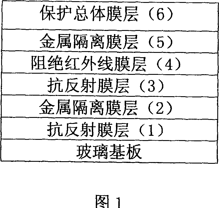
[0021] The anti-reflective coating is made of Si 3 N 4 ; Protect the overall film layer with Si 3 N 4 The film thickness of the anti-reflection film layer 1 is 21nm, the film thickness of the metal isolation film layer 2 is 2nm, the film thickness of the metal isolation film layer 5 is 2nm, the film thickness of the anti-reflection film layer 3 is 7nm, and the infrared film layer 4 is blocked The thickness of the film is 12nm, and the thickness of the overall protective film layer 6 is 50nm.
[0022] In production, the target material of the anti-reflection film layer 3 and the target material of the infrared blocking film layer 4 are placed in the same gas isolation chamber, and Ar and O 2 The weight percent content is respectively: 95% and 5%.
[0023]
product name
Can
See
Light
see through
Pass
Rate
%
purple
outside
Wire
see through
Pass
Rate
%
solar thermal...
Embodiment 2
[0033] The anti-reflective coating is made of Si 3 N 4 +TiO 2 ; Protect the overall film layer with SnO 2 +Si 3 N 4 The film thickness of anti-reflection film layer 1 is 30nm, and the film thickness of metal isolation film layer 2 is 1.5nm, and the film thickness of metal isolation film layer 5 is 1.5nm, and the film thickness of antireflection film layer 3 is 5nm, blocks infrared ray film The film thickness of the layer 4 is 8 nm, and the film thickness of the overall protective film layer 6 is 35 nm.
[0034] In production, the target material of the anti-reflection film layer 3 and the target material of the infrared blocking film layer 4 are placed in the same gas isolation chamber, and Ar and O 2 The weight percent content is respectively: 85% and 15%.
[0035]
Embodiment 3
[0037] The anti-reflective coating is made of Si 3 N 4 ; Protect the overall film layer with TiO 2 +Si 3 N 4 The film thickness of anti-reflection film layer 1 is 15nm, the film thickness of metal isolation film layer 2 is 5nm, the film thickness of metal isolation film layer 5 is 5nm, the film thickness of antireflection film layer 3 is 10nm, cuts off infrared film layer 4 The thickness of the film is 14nm, and the thickness of the overall protective film layer 6 is 60nm.
[0038] In production, the target material of the anti-reflection film layer 3 and the target material of the infrared blocking film layer 4 are placed in the same gas isolation chamber, and Ar and O 2 The weight percentage content is respectively: 90% and 10%.
[0039]
PUM
| Property | Measurement | Unit |
|---|---|---|
| Film thickness | aaaaa | aaaaa |
| Film thickness | aaaaa | aaaaa |
| Film thickness | aaaaa | aaaaa |
Abstract
Description
Claims
Application Information
 - R&D
- Intellectual Property
- Life Sciences
- Materials
- Tech Scout
- Unparalleled Data Quality
- Higher Quality Content
- 60% Fewer Hallucinations
Browse by: Latest US Patents, China's latest patents, Technical Efficacy Thesaurus, Application Domain, Technology Topic, Popular Technical Reports.
© 2025 PatSnap. All rights reserved.Legal|Privacy policy|Modern Slavery Act Transparency Statement|Sitemap|About US| Contact US: help@patsnap.com


