
Automatic foam eliminating machine

An automatic and mechanical device technology, applied in biochemical instruments, biochemical equipment and methods, enzymology/microbiology devices, etc., can solve the problems of no automatic control system, long foam swallowing time, environmental pollution, etc., to improve environmental protection benefit, harm reduction, emission reduction effect

Active Publication Date: 2012-07-04
北京博硕德恒科技开发有限公司
View PDF4 Cites 0 Cited by
  • Summary
  • Abstract
  • Description
  • Claims
  • Application Information

AI Technical Summary

Problems solved by technology

Its disadvantage is that the defoaming rake only installs a raking scraper on the top of the liquid surface in the tank to break the large bubbles on the surface into small bubbles, and the result is that the foam cannot be removed; but it has no choice but to use chemical agents (such as: defoamer) , vegetable oil) for defoaming, although the foam can be removed, one is that the cost is too high, and the other is that it pollutes the environment
[0003] I invented the utility model foam swallowing machine in 1999. Its patent number is: ZL99247539.2. It has been tested in some manufacturers successively. Its defoaming method is powered by sterile compressed air. Although this invention saves a lot of defoaming agent, it takes a long time to swallow the foam due to the limitation of the amount of straw. At the same time, it is not equipped with an automatic control system, and manual operation is required, which brings a lot of trouble to production.

Method used

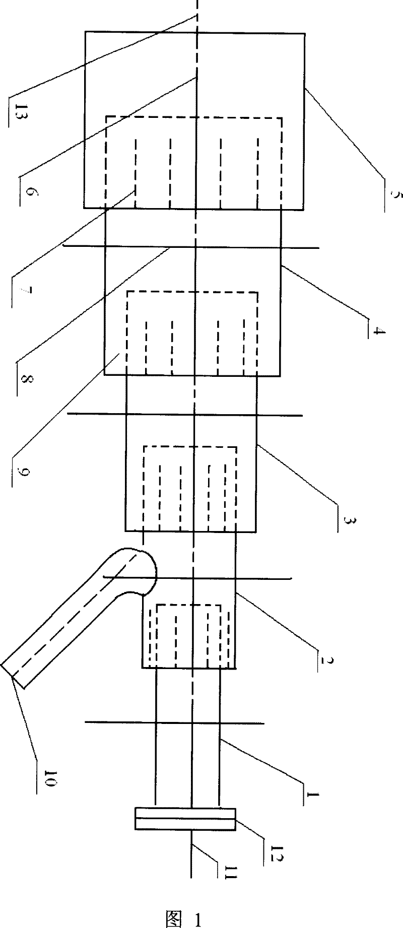
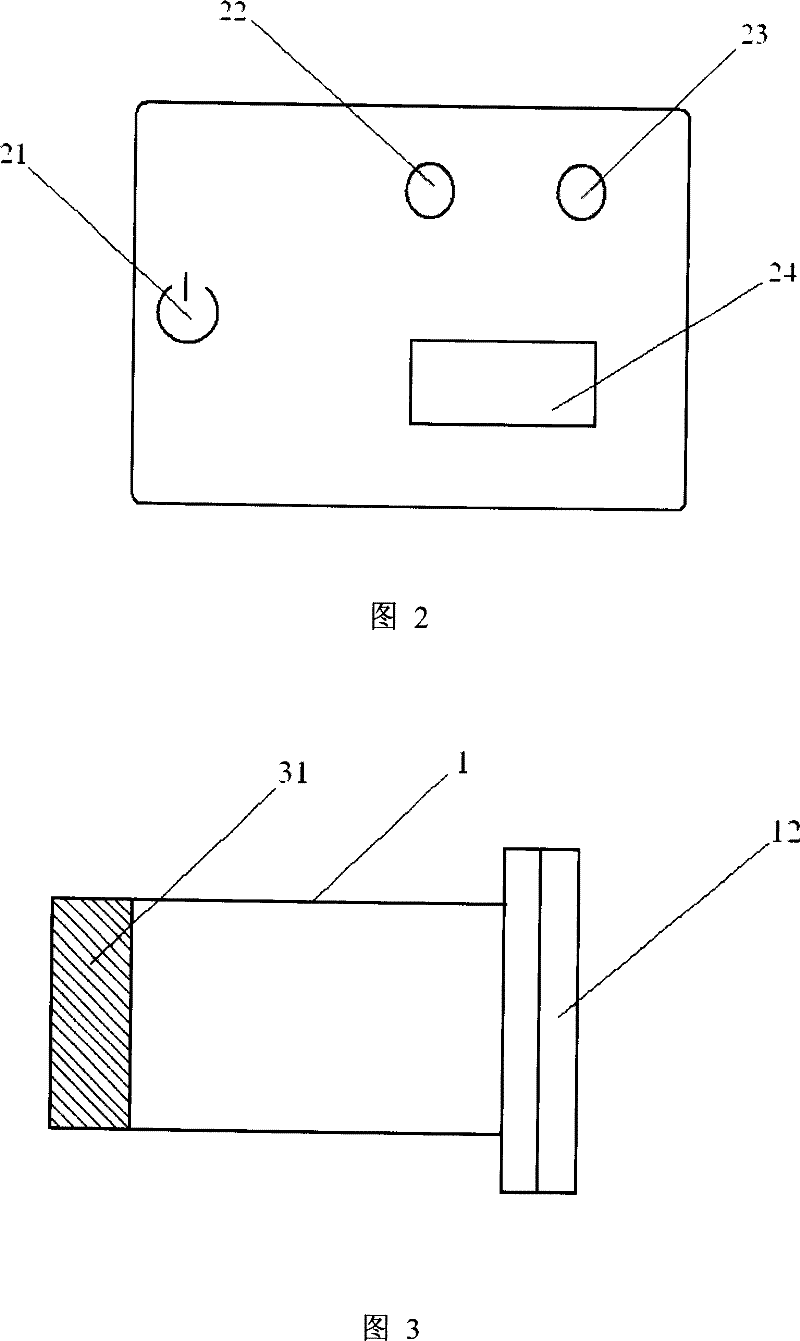
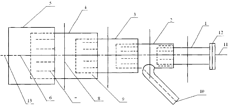

Image

  • Automatic foam eliminating machine
  • Automatic foam eliminating machine
  • Automatic foam eliminating machine

Examples


Embodiment Construction

[0023] The specific embodiments of the present invention will be further described below in conjunction with the drawings, which will be explained in more detail.

[0024] Such as figure 1 , 3 As shown, the present invention includes two parts: a mechanical device and an automatic control system. In the mechanical device, the first nozzle is connected to the second nozzle, the second nozzle is connected to the third nozzle, and the third nozzle is connected to the fourth nozzle. , The fourth nozzle is connected to the fifth nozzle. The five nozzles have different diameters and are connected to each other to form a horn-shaped spray chamber from thin to thick. At one end of the trumpet-shaped spray chamber, a thin first nozzle is set There is a constant velocity spiral device; the spray cavity is penetrated into the whole machine; this mechanical device is also provided with a rear suction pipe and an outer edge, wherein the rear suction pipe serves to balance the airflow, and the...


PUM


Abstract

The present invention discloses one kind of automatic foam eliminating machine used in fermentation process, and features that the automatic foam eliminating machine includes one mechanical device and one automatic control system. The mechanical device includes five nozzles of different sizes, rear sucking pipe, outer edge, spraying cavity and flanges; and the automatic control system is installed inside the operation chamber. The present invention is designed based on fluid mechanic principles, and has raised production efficiency and environment friendship.

Description

technical field [0001] The invention relates to a defoaming device, in particular to an automatic foam swallowing machine used in the fermentation process. Background technique [0002] At present, in the production process of citric acid, glutamic acid, lysine, enzyme preparations, antibiotics and other biological aerobic fermentation fields, a large number of foams are inevitably generated, and these foams must be removed, otherwise the production will be seriously affected. However, in real life, people generally use the traditional defoaming method, that is, the combination of defoaming rake and defoaming agent. Its disadvantage is that the defoaming rake only installs a raking scraper on the top of the liquid surface in the tank to break the large bubbles on the surface into small bubbles, and the result is that the foam cannot be removed; but it has no choice but to use chemical agents (such as: defoamer) , vegetable oil) for defoaming, although the foam can be remove...

Claims


Application Information

Patent Timeline
Patent Type & Authority Patents(China)
IPC IPC(8): C12M1/21
CPCC12M41/02
Inventor 吕建军王琳吕博佑
Owner 北京博硕德恒科技开发有限公司
Learn More