Supercharge Your Innovation With Domain-Expert AI Agents!

Elevator compensating cable

An elevator compensation and compensation cable technology, which is applied to textile cables, textiles and papermaking, etc., can solve the problem that the use effect is not as good as expected, and achieve the effect of small natural bending radius, simple guidance, and elimination of distortion.

Inactive Publication Date: 2007-03-21
朱思中
View PDF1 Cites 3 Cited by
  • Summary
  • Abstract
  • Description
  • Claims
  • Application Information

AI Technical Summary

Problems solved by technology

[0007] Therefore, the use effect of this compensation cable is not as expected, so it can only be used in low-speed elevators

Method used


Image

  • Elevator compensating cable
  • Elevator compensating cable
  • Elevator compensating cable

Examples


Embodiment Construction

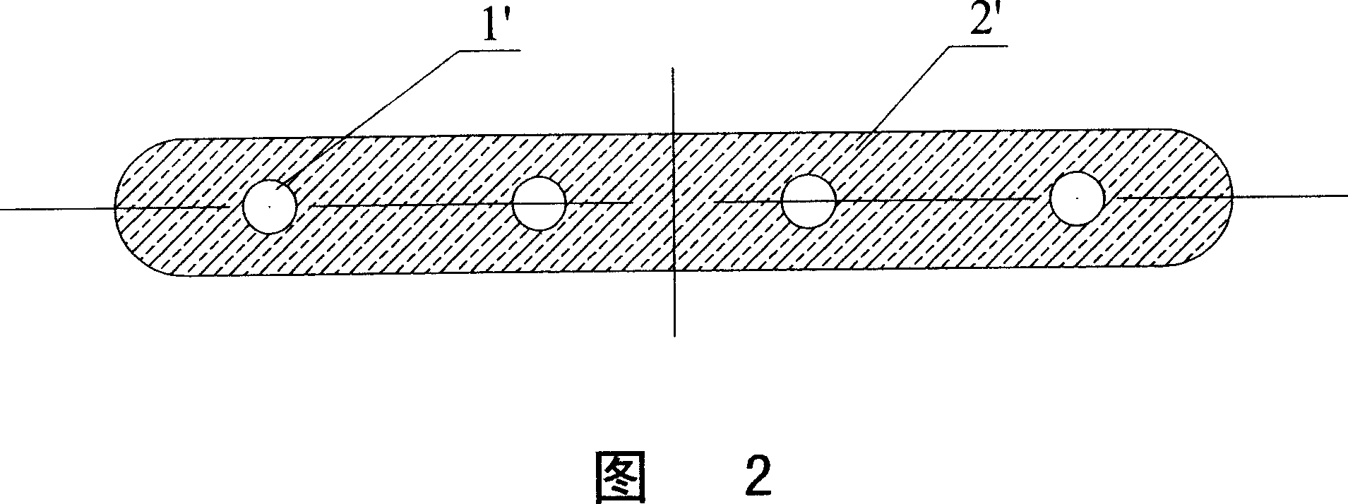
[0016] Referring to Fig. 2, embodiment one of the present invention, this scheme is the basic form of the present invention.

[0017] The elevator compensation cable is flat, and there are several thin steel wire ropes 1' inside, and the specifications, diameters and quantities of the steel wire ropes are determined according to the specific specifications of the compensation cable;

[0018] The periphery of steel wire rope 1 ' is the plastic 2 ' that contains metal particle or powder, and its proportioning also decides according to the specific specification of compensating cable.

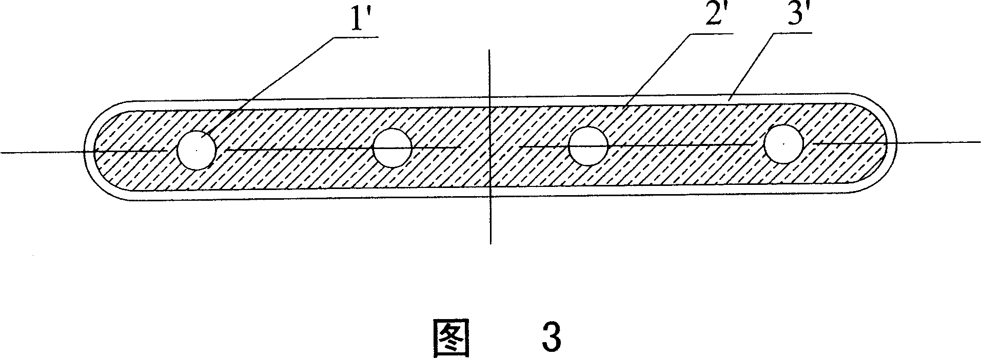
[0019] Referring to Fig. 3, Embodiment 2 of the present invention, which is an optimized form of the present invention. The difference between scheme two and scheme one is that the outermost layer of scheme two is plastic 3' without metal particles or powder, which can protect the core, improve the appearance of the compensation cable, and reduce the friction between the compensation cable and the...


PUM


Abstract

The present invention relates to a compensating cable for elevator. It is characterized by that the described compensating cable is made into flat form, its core portion has several steel wire ropes for bearing load and its exterior is covered with soft plastics containing metal granules or metal powder. Besides, its exterior also can be covered with soft plastics containing no metal granules or metal powder.

Description

technical field [0001] The invention relates to a traction elevator, in particular to an elevator compensation system. Background technique [0002] The function of the elevator compensation cable is to eliminate or reduce the torque change on the traction sheave caused by the length change of the suspension rope and the accompanying cable during the operation of the elevator. [0003] The traditional compensation chain is a ring chain, and the ropes made of soft fibers such as cotton and hemp are worn in the chain rings. The role of the rope is to reduce the noise from the chain when the elevator is running and to prevent the chain from knotting. Although it has the advantage of low price, it is not easy to guide, and when the elevator speed is high, noise and knotting cannot be avoided, so it is generally only used for low-speed elevators. [0004] Siecor Corporation of the United States introduced a Whisperflex compensation chain many years ago. The cross section of the...

Claims


Application Information

Patent Timeline
Patent Type & Authority Applications(China)
IPC IPC(8): D07B1/06D07B1/22
Inventor 朱思中
Owner 朱思中
Features
  • R&D
  • Intellectual Property
  • Life Sciences
  • Materials
  • Tech Scout
  • Unparalleled Data Quality
  • Higher Quality Content
  • 60% Fewer Hallucinations
Learn More