Mixed positioning method and mixed positioning terminal

A hybrid positioning and terminal technology, which is applied in the fields of computer network communication, wireless communication, electronic and electrical design and satellite positioning, can solve the problems of insufficient positioning accuracy, high satellite signal requirements, and inability to accurately determine the terminal position, and achieves a reduced accuracy requirement. Effect

Inactive Publication Date: 2007-03-21
孟详粤
View PDF0 Cites 11 Cited by
  • Summary
  • Abstract
  • Description
  • Claims
  • Application Information

AI Technical Summary

Problems solved by technology

[0011] The purpose of the present invention is to provide a hybrid positioning method and a hybrid positioning terminal (hereinafter referred to as the terminal) for realizing the method, so as to solve the problems existing in the existing positioning technology

Method used


Image

  • Mixed positioning method and mixed positioning terminal
  • Mixed positioning method and mixed positioning terminal
  • Mixed positioning method and mixed positioning terminal

Examples


Embodiment Construction

[0032] The present invention will be described in detail below in conjunction with the accompanying drawings.

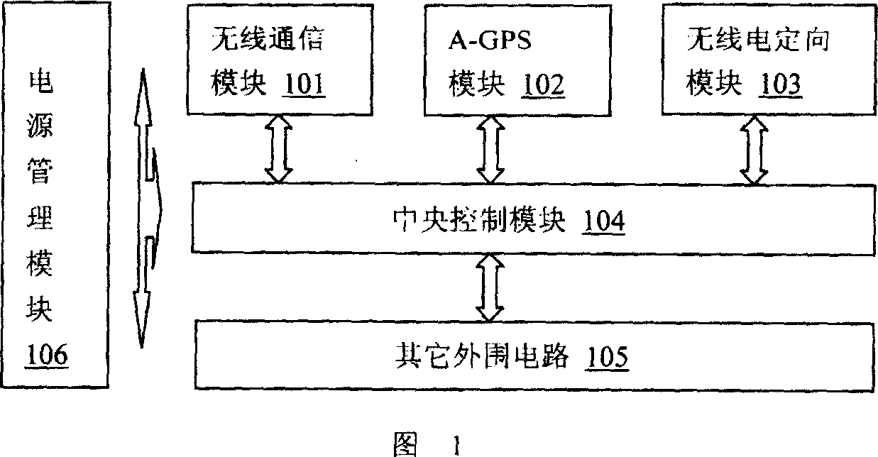
[0033] Please refer to FIG. 1 . FIG. 1 is a schematic structural diagram of an embodiment of a hybrid positioning terminal according to the present invention. include:

[0034] Wireless communication module 101: connected to and controlled by the central control module 104, responsible for wireless communication with the outside world, so as to realize the interaction of various information between the terminal and the remote server, and has the function of querying the terminal's power.

[0035] A-GPS module 102: It is a GPS signal receiver supporting the A-GPS positioning mode, which is connected with the central control module 104 and controlled by it, and completes the role of the mobile station to be positioned in the A-GPS positioning technology, including capturing satellite signals and performing Pseudorange measurement, etc.

[0036] Radio directional modu...


PUM


Abstract

A mixed positioning method includes starting up normal assisting - positioning process first by mixed positioning terminal when positioning request sent from user is received, sending request of positioning assistance data and radio network cell identification number to server, catching satellite signal and measuring pseudo-distance by GPS signal receiver after assistance data is obtained, sending measured result and radio network cell identification number again to server then carrying out treatment on data by server. The mixed positioning terminal used for realizing said method is also disclosed.

Description

technical field [0001] The present invention relates to technical fields such as wireless communication, computer network communication, electronic and electrical design, satellite positioning, etc., and more mainly relates to a hybrid positioning method integrating A-GPS satellite positioning, wireless mobile communication network and radio transmission directional technology. Background technique [0002] The current GPS (Global Positioning System) positioning mainly uses the pseudo-range measurement method, which is based on the following formula: [0003] ρ 1 = ( x 1 - x u ...

Claims


Application Information

Patent Timeline
IPC IPC(8): H04Q7/38G01S5/02H04W64/00
Inventor 孟详粤
Owner 孟详粤
Why Eureka
Try Eureka