Small section branch-flow measuring method for large-diameter gas flow and apparatus thereof

A technology for gas flow and measuring device, which is applied in the direction of measuring device, measuring flow/mass flow, liquid/fluid solid measurement, etc. Flexibility of use, ease of assembly and operation, great effect of flexibility of use

Inactive Publication Date: 2007-03-28
MEMSIC SEMICON WUXI
View PDF1 Cites 12 Cited by
  • Summary
  • Abstract
  • Description
  • Claims
  • Application Information

AI Technical Summary

Problems solved by technology

[0005] The present invention mainly solves the problem existing in the prior art that when measuring the fluid flow in a large-diameter pipeline, because it is easily affected by the flow state, the requirement for the flow state of the fluid is relatively high, the measurement accuracy is low, the sensor is easily disturbed, and cannot It truly reflects the technical problems of fluid flow, etc.; it provides a method that is easy to implement, can effectively eliminate flow state interference, has low requirements on flow state, and can accurately measure fluid flow in large-diameter pipelines even without rectification devices, with high measurement accuracy. Method and device for small-section split flow measurement of large-diameter gas flow
[0007] Another purpose of the present invention is to solve the technical problems existing in the prior art that it is difficult to assemble, the operation is difficult, the rectification device adopts an integrated design, the flexibility of use is poor, and the length cannot be adjusted according to needs; it provides an easy-to-assemble and operation, the length of the rectification device can be adjusted according to actual needs, so as to adapt to various working occasions, and the method and device for measuring the small cross-section shunt flow of large-caliber gas flow with great flexibility

Method used


Image

  • Small section branch-flow measuring method for large-diameter gas flow and apparatus thereof
  • Small section branch-flow measuring method for large-diameter gas flow and apparatus thereof
  • Small section branch-flow measuring method for large-diameter gas flow and apparatus thereof

Examples


Embodiment 1

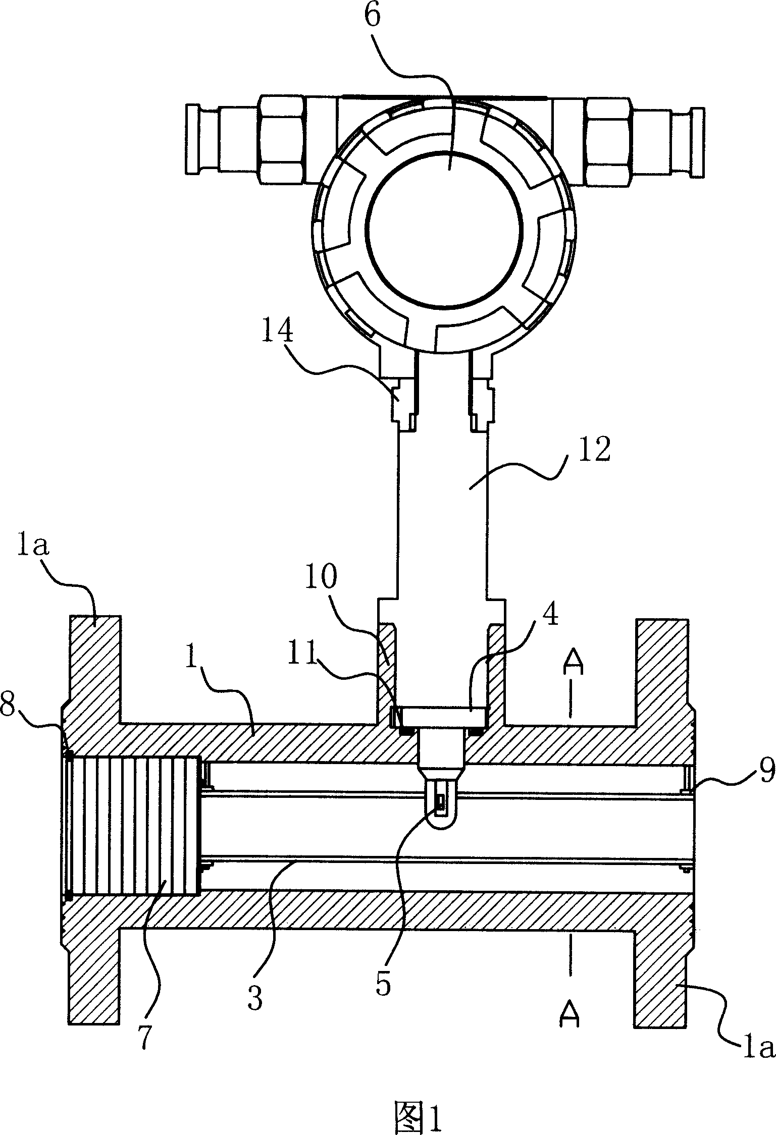
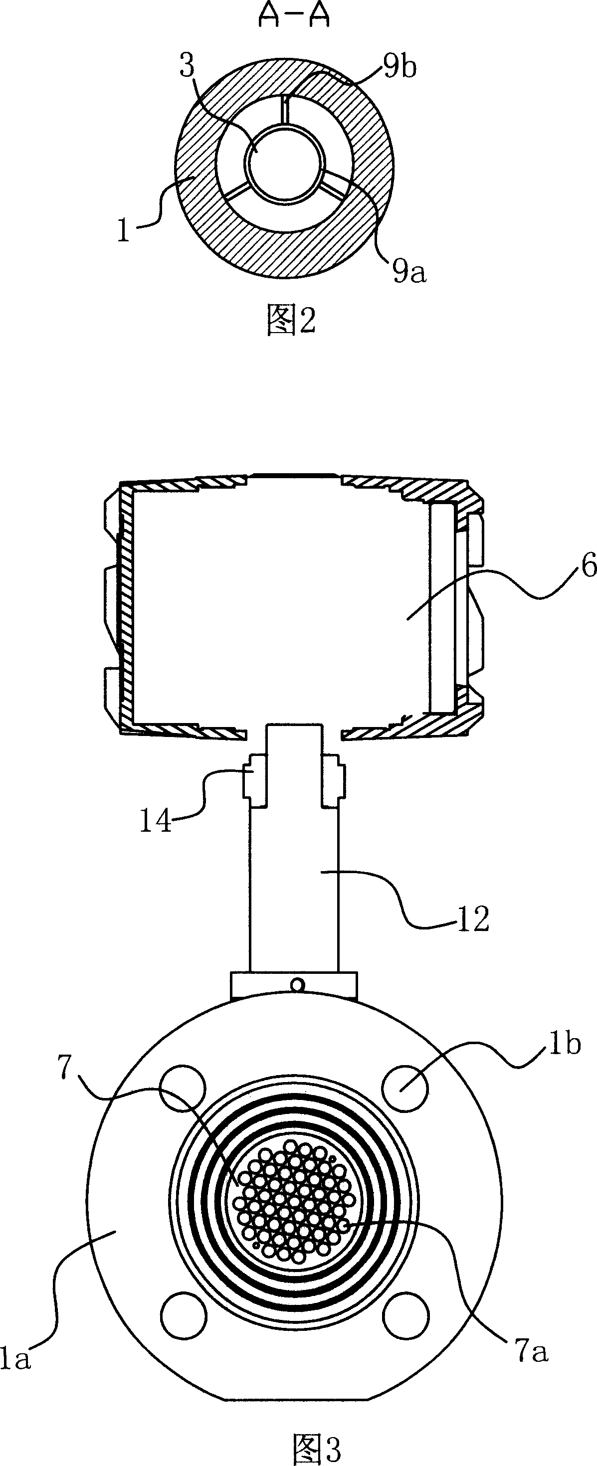
[0031] The small-section shunt measurement method for large-diameter gas flow includes the following measurement steps: a. Proportional shunt: at least one shunt pipe with a smaller diameter is set in the large-diameter pipeline, and the airflow to be measured in the large-diameter pipeline is divided by the shunt device. Divert the flow into the shunt according to the preset ratio; b. Flow measurement of the shunt: set a flow sensor in the shunt, and detect the gas flow in the shunt through the flow sensor; c. Flow conversion: measure the flow value in the shunt according to the set value. The given diversion ratio is converted into the total gas flow rate in the large-diameter pipeline.

[0032] In this embodiment, a shunt pipe is provided, and the shunt pipe is arranged on the central axis of the pipeline. The flow sensor used to measure the flow is a thermal mass flow sensor and rectifies the air flow before it is proportionally split.

[0033] The above method is realize...

Embodiment 2

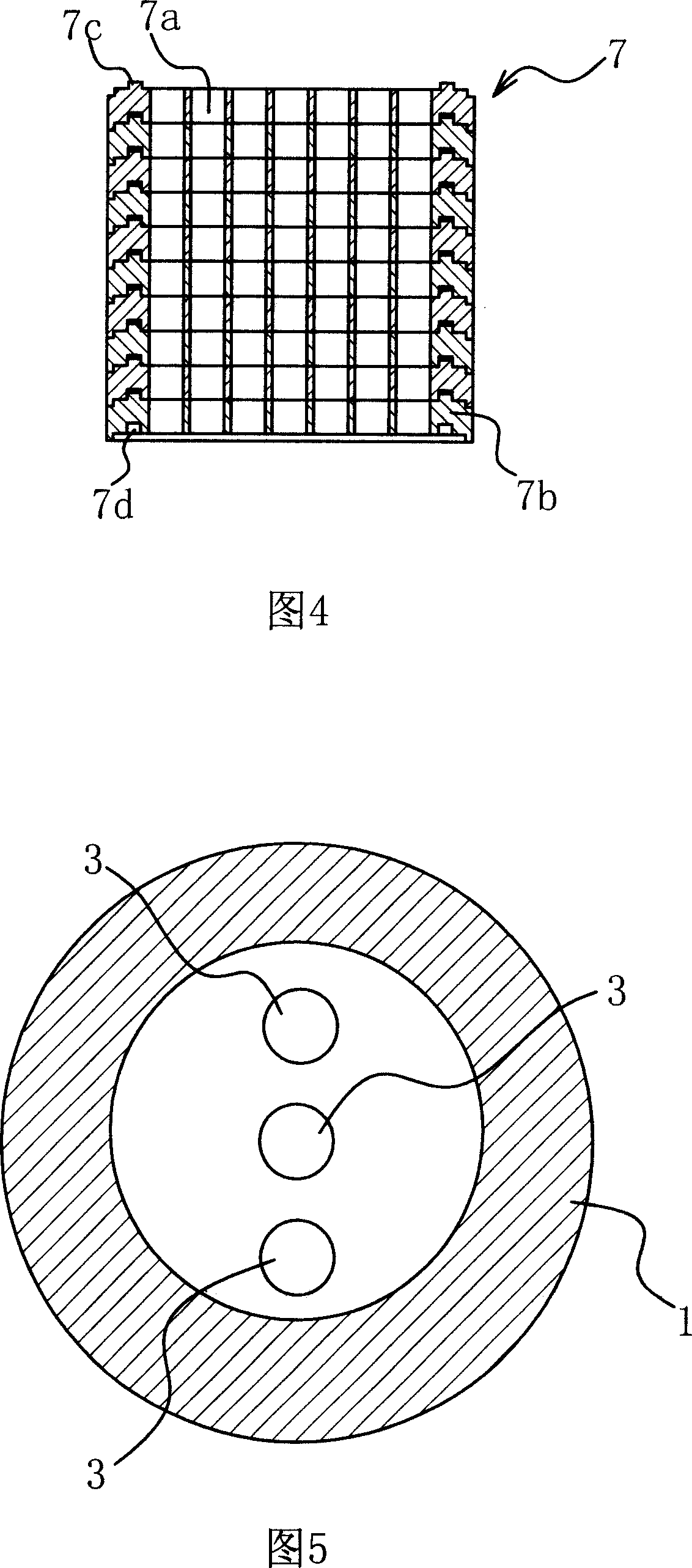
[0037] As shown in FIG. 5 , three shunt pipes 3 are provided in the ventilation pipe 1 . The shunt pipes 3 are evenly distributed in the ventilation pipe 1 , and one shunt pipe 3 is arranged on the central axis of the ventilation pipe 1 . Take the average value of the shunt flow rate measured in each shunt pipe 3, and use the average value to calculate the total gas flow rate in the large-diameter pipeline according to the shunt ratio. The rest are similar to those in Embodiment 1, and will not be repeated here.

Embodiment 3

[0039] In this embodiment, the values ​​of the divided flow measured in each of the divided pipes are accumulated, and the accumulated value is used to calculate the total gas flow rate in the large-diameter pipe according to the divided flow ratio. The rest are similar to those in Embodiment 2, and will not be repeated here.

[0040] In the present invention, the signal processing process and the proportional calculation process of the flow sensor are well known in the prior art, and can be easily implemented by those skilled in the art, which will not be described herein.


PUM


Abstract

This invention relates to a test method for small sections of large caliber gas flows and an informed structure of the device including the following measurement steps: a, shunting in proportion, b, testing the shunt flow, c, converting the flow, in which, a shunt pipe is set in the channel of a ventilation pipeline of small aperture and parallel to the pipeline, one end of a sensor frame passes through the wall of the shunt tube and a sensor is fixed at the end connected with a measurement meter and a shunt device shunting in proportion is set at an end of the shunt tube. Advantage: taking part of sections with stable fluid in a large aperture pipeline as the sample for test and the test is accurate.

Description

technical field [0001] The invention relates to the field of gas flow detection, in particular to a small cross-section shunt measurement method and device for large-diameter gas flow. Background technique [0002] When detecting the flow rate of fluids such as gas and liquid in the pipeline, a flow sensor is usually arranged in the flow path, and the flow rate measured by the flow sensor is multiplied by the cross-sectional area of ​​the flow path to calculate the flow rate. In the case of small diameter, due to the better flow state of the fluid, the measurement accuracy is relatively high. However, once the above method is applied to the occasion of large diameter, the measurement error will increase significantly. The reason is that in the pipeline with large diameter, the flow state of the fluid will change, and complex flow state conditions such as eddy current and turbulent flow will easily occur, and the flow velocity distribution will be asymmetrical, so that there...

Claims


Application Information

Patent Timeline
Patent Type & Authority Applications(China)
IPC IPC(8): G01F1/00G01F15/00
Inventor 毛巨林赵文宏金耀青
Owner MEMSIC SEMICON WUXI
Why Eureka
Try Eureka