[0033] In order to further explain the technical means and effects of the present invention to achieve the intended purpose of the invention, in conjunction with the accompanying drawings and preferred embodiments, the specific repeater suitable for the time division duplex mobile communication system proposed in accordance with the present invention will be described below. The detailed description of the implementation, structure, features and effects is as follows.
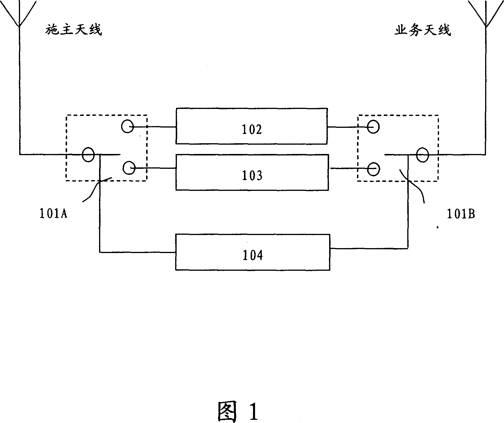
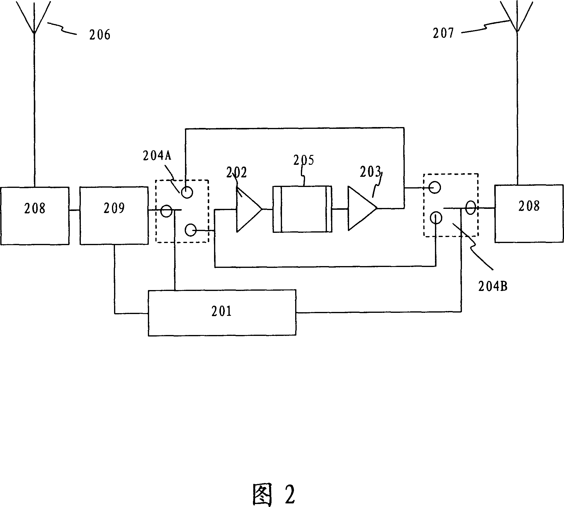
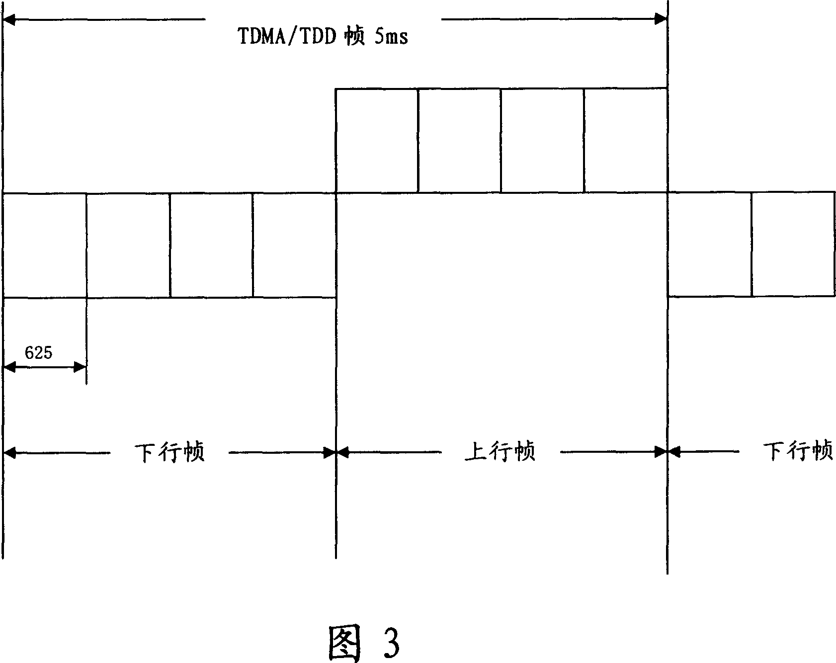
[0034]The core principle of the present invention is: in the mobile communication system using the TDD system, the uplink signal and the downlink signal between the base station and the terminal are at different times and maintain a strict synchronization relationship, so it only needs to pass through the radio frequency switch array To control, you can share the low-noise amplifier, digital gain controller and linear power amplifier time-sharing as the uplink or downlink amplifier. Even if the repeater has different installation positions and different signal coverage requirements, it is completely possible to adjust its uplink gain and downlink gain through the digital gain controller to meet the requirements of the system. Since the uplink and downlink share the amplifier, the sequential circuit for controlling the on and off of the uplink and downlink amplifier is omitted, and the amplifier is also easier to design and process.
[0035] Please refer to Figure 2, which is a schematic diagram of the system structure of the repeater of the present invention. The components of the repeater of the present invention include: time synchronization controller 201, low noise amplifier 202, linear power amplifier 203, radio frequency electronic switch arrays 204A, 204B, digital gain controller 205, donor antenna 206, service antenna 207, filter 208. Coupler 209.
[0036] In the initial working state, the radio frequency electronic switch array 204 sets the low noise amplifier 202, the linear power amplifier 203, and the digital gain controller 205 to work in downlink.
[0037] If it is still working in the downlink state, the state of the radio frequency electronic switch arrays 204A and 204B remains unchanged. At this time, the downlink signal of the base station received from the donor antenna 206 feeds the coupling signal to the time synchronization controller 201 through the coupler 209. Down-conversion, intermediate-frequency filtering, high-speed A/D change, so as to obtain the downlink baseband signal, decode it, and further obtain the control signal of the radio frequency electronic switch array 204A, 204B and the digital gain controller 205 through the sequential circuit. The downlink signal is amplified by the filter 208, the low noise amplifier 202, the digital gain controller 205, and the linear power amplifier 203, and is transmitted through the service antenna 207.
[0038] If it becomes an uplink state at this time, the radio frequency electronic switch arrays 204A and 204B will set the low noise amplifier 202, the linear power amplifier 203, and the digital gain controller 205 to work in the uplink. The uplink signal is amplified by the filter 208, the low noise amplifier 202, the digital gain controller 205, and the linear power amplifier 203, and transmitted through the donor antenna 206. The coupler 209 installed at the donor antenna 206 can detect the input power of the uplink signal as a digital signal. The gain control signal of the gain controller 205 in the uplink state.
[0039] It should be noted that the time synchronization controller 201 is composed of a radio frequency down-converter and a baseband chip (ASIC, DSP). Its basic working principle is to convert the high-frequency carrier signal of the mobile communication system coupled from the base station or received from the air into The intermediate frequency carrier signal is processed by the baseband chip for intermediate frequency filtering, A/D conversion and decoding, and the uplink and downlink control signals synchronized in time with the SCDMA, PHS or TD-SCDMA base station are output. Its function is to make the repeater go up and down. Line switching is synchronized with the base station.
[0040] The low-noise amplifier 202 is used as a pre-stage of the amplification link to realize low-noise amplification of uplink or downlink signals, and its technical performance indicators such as operating frequency, bandwidth, gain, etc. should be adapted to the requirements of the applied mobile communication system.
[0041] The linear power amplifier 203 is used as the final stage of the amplification link to realize the power amplification of the uplink or downlink signal, and its technical performance indicators such as operating frequency, bandwidth, gain, etc. should be adapted to the requirements of the applied mobile communication system.
[0042] The digital gain controller 205 is an additional function provided to adapt the equipment to the different requirements on the uplink and downlink output power in various environments. It can be controlled locally or remotely, and through time synchronization control signals, to achieve the combination of uplink and downlink gains. .
[0043] The radio frequency electronic switch array 204 combines each unit into an uplink amplifying link and a downlink amplifying link under the action of a time synchronization control signal. The main technical indicators of the radio frequency switch are operating frequency, switching time and insertion loss.
[0044] The filter 208 is an additional device to ensure the quality of the uplink and downlink signals.
[0045] The coupler 209 is an additional device for extracting uplink and downlink signals as the input of the time synchronization controller 201 and the input of the digital gain controller 205.
[0046] Please refer to FIG. 3 and Table (1). The PHS system is taken as an example to illustrate the state of the switches in the uplink frame and the downlink frame of the present invention. The PHS system uplink frame and downlink frame time are each 2.5ms. In the standby state, in order to achieve time synchronization with the system base station, the repeater of the present invention should be in the downlink working state, and the other time shall be in the uplink working state according to the time synchronization requirements. Or down working status.
[0047] Table 1)
[0048] Time
[0049] The repeater of the present invention is aimed at different systems such as PHS, SCDMA, TD-SCDMA, and its key technical parameter requirements are different.
[0050] Table (2) ~ Table (6) and Article (7) give the following requirements for the technical indicators (recommended values) of each component of the repeater (take the PHS system as an example) of the present invention:
[0051] Table (2) Low noise amplifier
[0052] Operating frequency range
[0053]
[0054] Table (3) Linear power amplifier
[0055] Operating frequency range
[0056] Output standing wave
[0057] Table (4) RF switch array
[0058] Operating frequency range
[0059] Table (5) Filter
[0060] Operating frequency range
[0061] Table (6) Coupler
[0062] working frequency
[0063] (7) Monitoring technical indicators
[0064] Control mode: remotely through the PHS mobile phone module, the near-end is connected to the repeater through the serial port.
[0065] Monitoring and alarm items: door opening, standing wave, over power, DC voltage, over temperature, working status and out-of-step alarm of the synchronization control module.
[0066] Control items: uplink and downlink attenuation; switch power amplifier, alarm enable and shield.
[0067] Query function: The operation and maintenance system can query the following parameters: working status; uplink and downlink gain, output power; record query, including operation record and fault record query, etc.; base station ID number used, base station signal quality (bit error rate), reception Base station signal level, etc.
[0068] Table (8) is the main technical indicators used in the TD-SCDMA, PHS, SCDMA mobile communication system of the repeater of the present invention.
[0069] Table (8)
[0070] main indicators
[0071] The above are only the preferred embodiments of the present invention, and are not intended to limit the present invention in any form. Although the present invention has been disclosed as above in preferred embodiments, it is not intended to limit the present invention. Anyone familiar with the profession Those skilled in the art, without departing from the scope of the technical solution of the present invention, can use the technical content disclosed above to make slight changes or modification into equivalent embodiments with equivalent changes, but any content that does not depart from the technical solution of the present invention is based on the present invention Any simple modifications, equivalent changes and modifications made to the above embodiments are still within the scope of the technical solutions of the present invention.