Multilayer piezoelectric element and its manufacturing method

A piezoelectric element and manufacturing method technology, applied in the manufacture/assembly of piezoelectric/electrostrictive devices, electrical components, piezoelectric/electrostrictive/magnetostrictive devices, etc., can solve the problem of driving stop, piezoelectric body Improve durability by eliminating problems such as supply voltage and cracks

Active Publication Date: 2007-03-28
KYOCERA CORP
View PDF3 Cites 6 Cited by
  • Summary
  • Abstract
  • Description
  • Claims
  • Application Information

AI Technical Summary

Problems solved by technology

[0013] First, since the active layer undergoes repeated dimensional changes during driving, when driving continuously for a long period of time under high electric field and high pressure, the external electrode and the piezoelectric body may peel off, or the external electrode itself may be cracked. Contact failure may occur at the connection between the external electrode and the internal electrode
Therefore, voltage cannot be supplied to some piezoelectric bodies, and if used for a long time, the displacement characteristics will change, sparks will be generated, and the drive will stop.
[0014] In recent years, small multi-layer piezoelectric elements have been driven continuously for a long period of time by applying a higher electric field in order to obtain a large displacement. Therefore, such a problem has become apparent.
[0015] In addition, in the inert layer disclosed in Patent Document 3, although the shrinkage difference between the active layer and the inert layer is alleviated, when a high voltage is applied, especially in the case of continuous driving for a long time, the electrodes forming the inert layer 62 Cracks occur at the interface between 61 and the piezoelectric layer (active part) 63, and there is a problem in durability

Method used


Image

  • Multilayer piezoelectric element and its manufacturing method
  • Multilayer piezoelectric element and its manufacturing method
  • Multilayer piezoelectric element and its manufacturing method

Examples


Embodiment approach 1

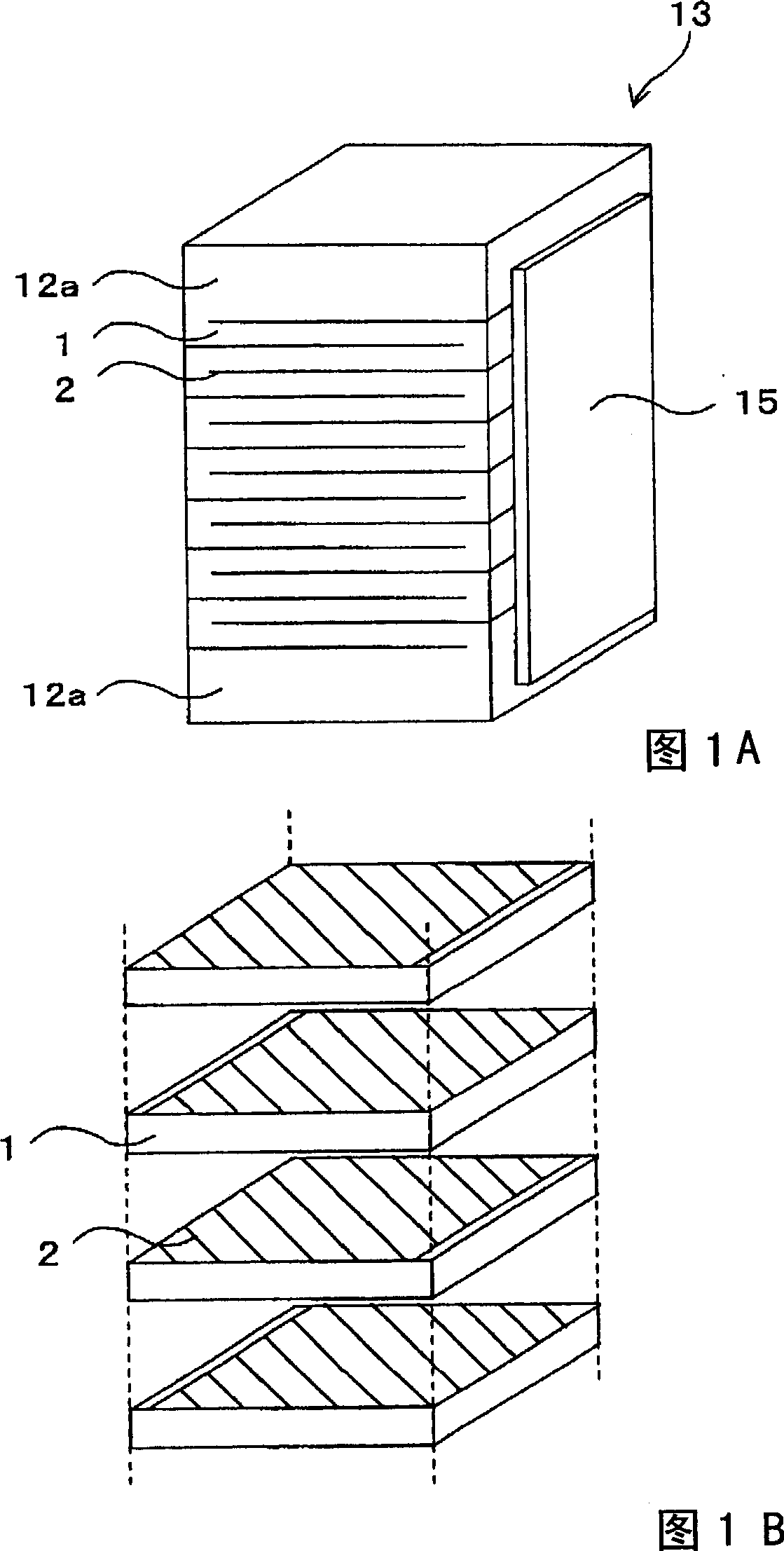
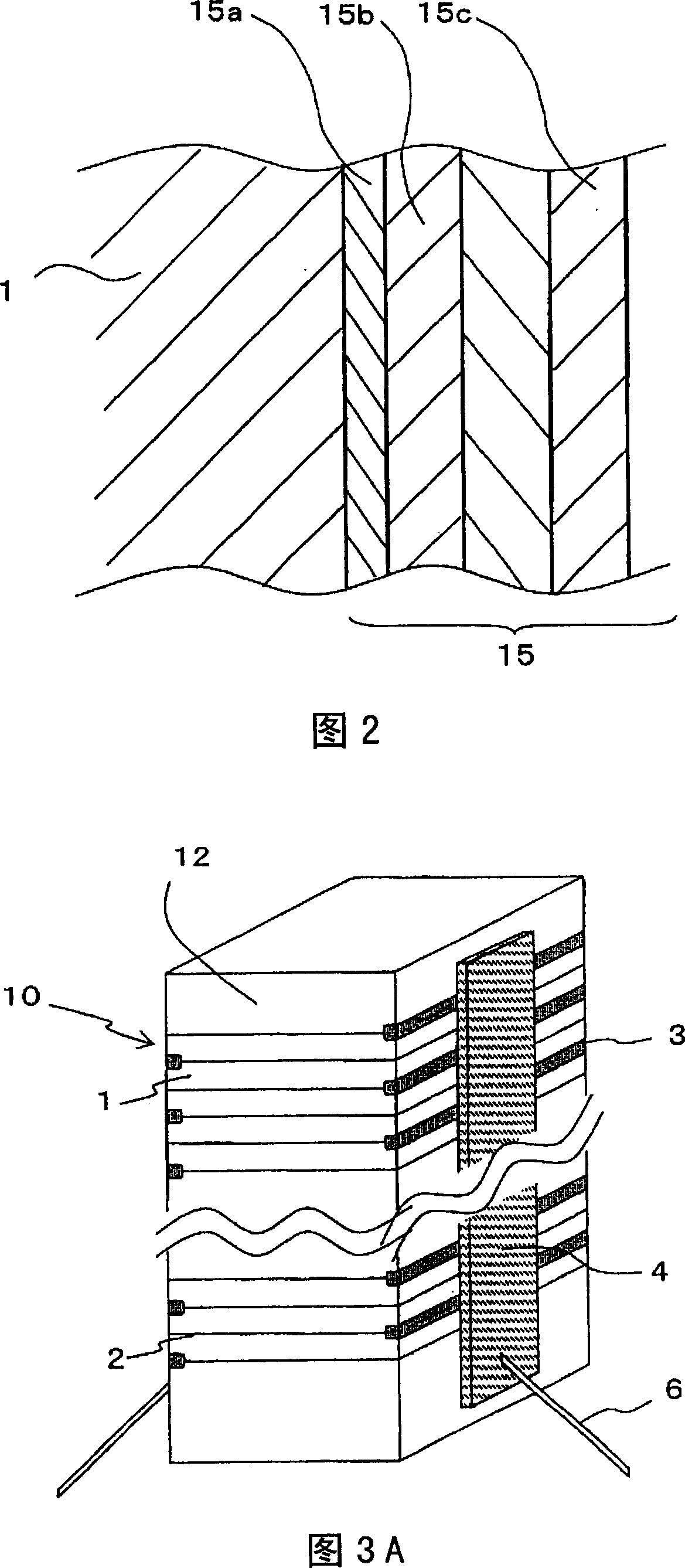
[0048] 1A and B are diagrams showing the configuration of a multilayer piezoelectric element according to Embodiment 1 of the present invention, wherein FIG. 1A is a perspective view, and FIG. 1B is a three-dimensional development showing a stacked state of a piezoelectric layer and an internal electrode layer. picture. In addition, FIG. 2 is an enlarged cross-sectional view showing a multilayer structure of external electrodes formed on the side surfaces of the piezoelectric body of the multilayer piezoelectric element of the present invention.

[0049] The multilayer piezoelectric element of Embodiment 1 is formed on a pair of opposing side surfaces of a laminated body 13 formed by alternately laminating piezoelectric bodies 1 and internal electrodes 2 as shown in FIGS. 1A and 1B . The external electrodes 15 expose the ends of the internal electrodes 2 every other layer on the side surfaces of the laminated body 13 where the external electrodes 15 are formed, and the externa...

Embodiment approach 2

[0083] Next, a multilayer piezoelectric element according to Embodiment 2 of the present invention will be described.

[0084] The basic structure of the active part 11 in the laminated body 10 of the multilayer piezoelectric element according to the second embodiment is the same as that of the multilayer piezoelectric element according to the first embodiment, and is characterized by the configuration of the inert layer 12 .

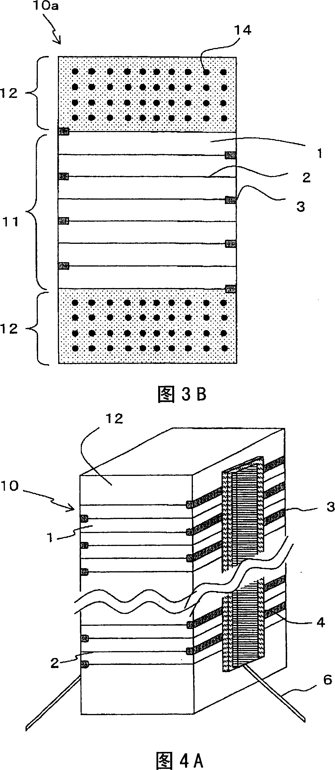
[0085] 3A and 3B are diagrams showing the configuration of a multilayer piezoelectric element according to Embodiment 2 of the present invention, wherein FIG. 3A is a perspective view, and FIG. A cross-sectional view of the lamination state of the protective layer.

[0086] In addition, as shown in FIGS. 3A and 3B , in the multilayer piezoelectric element according to the second embodiment, on the side surface of the active part 11 in which the piezoelectric body 1 and the internal electrode 2 are alternately laminated, there is formed a layer for  out...

Embodiment approach 3

[0151] Hereinafter, the injection device of the present invention will be described. This injection device is constructed using the multi-layer piezoelectric element of the present invention.

[0152] FIG. 6 shows the spraying device of the present invention. A spray hole 33 is provided at one end of a container 31. In addition, a needle valve 35 capable of opening and closing the spray hole 33 is housed in the container 31.

[0153] A fuel passage 37 is provided so as to communicate with the injection hole 33 , and the fuel passage 37 is connected to an external fuel supply source, and fuel is normally supplied to the fuel passage 37 at a constant high pressure. Therefore, when the needle valve 35 opens the injection hole 33, the fuel supplied to the fuel passage 37 is injected at a constant high pressure into a fuel chamber (not shown) of the internal combustion engine.

[0154] In addition, the diameter of the upper end portion of the needle valve 35 is enlarged, and it is...


PUM


Abstract

A multilayer piezoelectric element excellent in durability comprises a multilayer body and external electrodes. The multilayer body has an active portion which is formed by alternating at least one piezoelectric body and internal electrodes including first and second internal electrodes and expands / contracts depending on the voltage applied between the first and second internal electrodes. The external electrodes are formed on two side surfaces of the multilayer body. One of the external electrodes is connected to the first internal electrode, and the other is connected to the second internal electrode. Each external electrode is composed of three or more layers including a first layer in contact with the side surface of the multilayer body and a second layer formed on the first layer.

Description

technical field [0001] The present invention relates to a multilayer piezoelectric element (hereinafter also simply referred to as "element"), for example, to a fuel injection device mounted in an automobile engine, a liquid injection device such as an ink jet, a precision positioning device such as an optical device, or a vibration prevention device, etc. Drive elements in combustion pressure sensors, shock sensors, acceleration sensors, load sensors, ultrasonic sensors, pressure sensitive sensors, yaw rate sensors, etc., and sensor elements mounted in piezoelectric gyroscopes, piezoelectric switches, piezoelectric Multilayer piezoelectric elements used as circuit elements in electric transformers, piezoelectric circuit breakers, etc. Background technique [0002] Conventionally, a multilayer piezoelectric actuator in which piezoelectric bodies and internal electrodes are alternately laminated is known as a multilayer piezoelectric element. Multilayer piezoelectric actuato...

Claims


Application Information

Patent Timeline
Patent Type & Authority Applications(China)
IPC IPC(8): H01L41/083F02M51/00F02M51/06H01L41/22H02N2/00H01L41/187H01L41/257H01L41/27
Inventor 中村成信鹤丸尚文冈村健
Owner KYOCERA CORP
Why Eureka
Try Eureka