Heating bed structure, vacuum drying system therewith and manufacture thereof

A vacuum drying and drying technology, which is applied in the vacuum drying system, the process of manufacturing a bed structure, and the structural field of the heating bed, which can solve the problems of easy failure of welds and damage to fur

Inactive Publication Date: 2007-04-04
OFFICINE DI CARTIGLIANO SPA
View PDF1 Cites 7 Cited by
  • Summary
  • Abstract
  • Description
  • Claims
  • Application Information

AI Technical Summary

Problems solved by technology

However, this bed also has drawbacks, because at the end of the process, during retrieval, the edges of the holes can damage the pelts as they are dragged
[0013] Moreover, since the suction hole is substantially all the way through the cylindrical sleeve of the heating zone, and it is welded to the cover plate that delimits the chamber horizontally, the welds at the periphery are often prone to failure and require maintenance and further repairs

Method used


Image

  • Heating bed structure, vacuum drying system therewith and manufacture thereof
  • Heating bed structure, vacuum drying system therewith and manufacture thereof
  • Heating bed structure, vacuum drying system therewith and manufacture thereof

Examples


Embodiment Construction

[0031] Detailed description of preferred embodiments

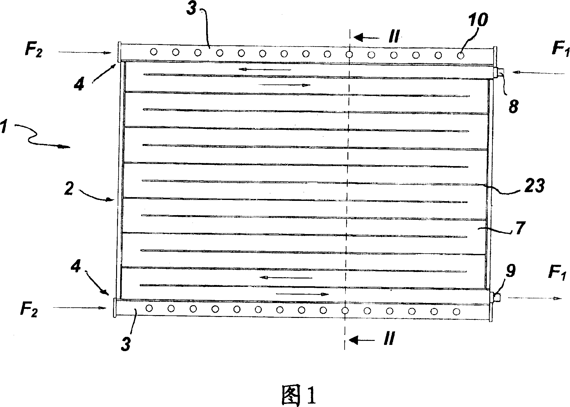
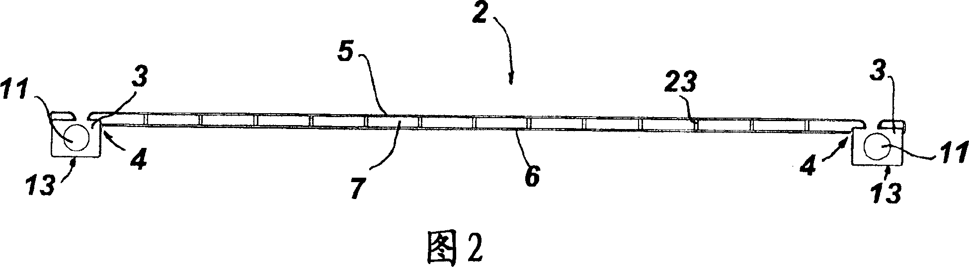
[0032] Referring to the above-mentioned drawings, the structure of the present invention, usually indicated by the number 1, basically includes one, preferably two stations 2 for heating the product to be dried, a collector 3 for steam released therefrom, It is arranged around at least one of its side straps 4.

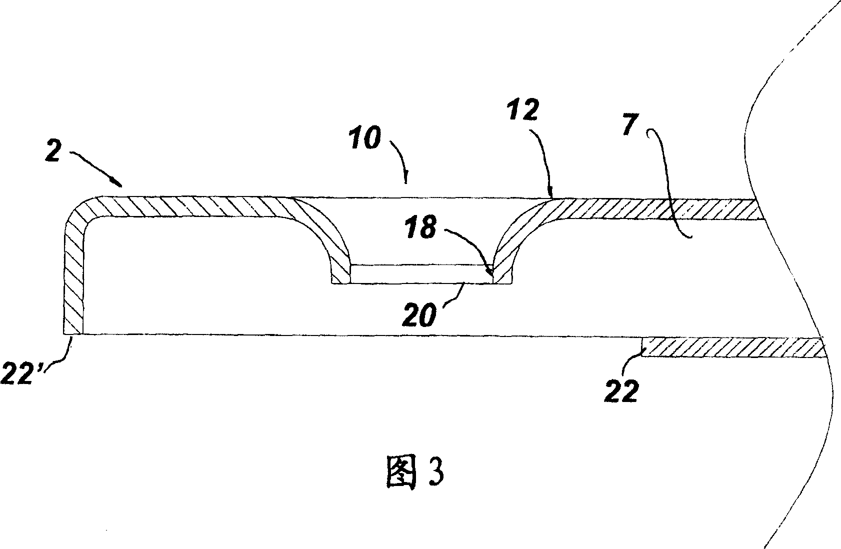
[0033] The table 2 basically includes at least a top disk 5 and a bottom disk 6 which are opposed to and spaced apart from each other to form a heat exchange chamber 7.

[0034] This chamber has an inlet pipe 8 and an outlet pipe 9 for circulating heating fluid F therein. 1 .

[0035] As it circulates in the chamber 7, these fluids will transfer heat through the tray 5 to the product to be dried, and the product will gradually lose moisture.

[0036] The steam released from the fur is absorbed into the collector 3 having a plurality of suction holes 10 through suitable external elements. The collector 3 has suitable e...


PUM


Abstract

An improved heating bed structure, especially a vacuum drying system for fur, leather and the like comprises a table for heating products to be dried with a top dish, a bottom dish and a heating chamber, inlet and outlet pipelines connected with the above chamber for the heater fluid there, a suction inlet of steam released when fur is heated, at least one steam collector, at least a condenser disposed inside the collected capable of making the following freezing liquid flow inside and a unit for connecting with at least one collector and the outside steam suction element.

Description

Technical field [0001] The invention is applied to the field of leather equipment, and particularly relates to an improved heating bed structure on a vacuum drying system. [0002] The invention further relates to a process for manufacturing a bed structure. [0003] Finally, the present invention relates to a vacuum drying system incorporating such a structure. Background technique [0004] Vacuum drying equipment for industrial fur, leather and similar products has been known for many years. [0005] These devices usually include at least one chamber for drying the product to be dried, which is basically composed of a heating bed and a sealing cover. [0006] Typically, the heating bed is an empty metal table forming a chamber, and the chamber is heated by a high-temperature fluid, such as water supplied by a heat exchanger. Along the edge of the heating table, there are vapor collectors, which consist of tube bundles with a fluid coolant, such as frozen water, which actually a...

Claims


Application Information

Patent Timeline
Patent Type & Authority Applications(China)
IPC IPC(8): F26B9/06F26B3/06F26B25/18
Inventor 安东尼奥·波拉托
Owner OFFICINE DI CARTIGLIANO SPA
Why Eureka
Try Eureka