Electronic equipment cooling plant and electronic equipment

A technology for electronic equipment and cooling devices, which can be used in household refrigeration devices, lighting and heating equipment, cooling/ventilation/heating transformation, etc. It can solve the problems of air exhaustion and achieve the effect of reducing space

Inactive Publication Date: 2007-04-04
SANYO ELECTRIC CO LTD
View PDF1 Cites 6 Cited by
  • Summary
  • Abstract
  • Description
  • Claims
  • Application Information

AI Technical Summary

Problems solved by technology

Therefore, there is a problem that the air discharged from the cooling device cannot be discharged in any direction.

Method used


Image

  • Electronic equipment cooling plant and electronic equipment
  • Electronic equipment cooling plant and electronic equipment
  • Electronic equipment cooling plant and electronic equipment

Examples


Embodiment Construction

[0031]Hereinafter, embodiments of the present invention will be described in detail with reference to the drawings. In the present invention, a notebook computer is described as an example of an electronic device, but this embodiment can also be applied to other electronic devices. For example, this embodiment mode can also be applied to a desktop computer, a PAD (Personal Digital Assistant), or the like.

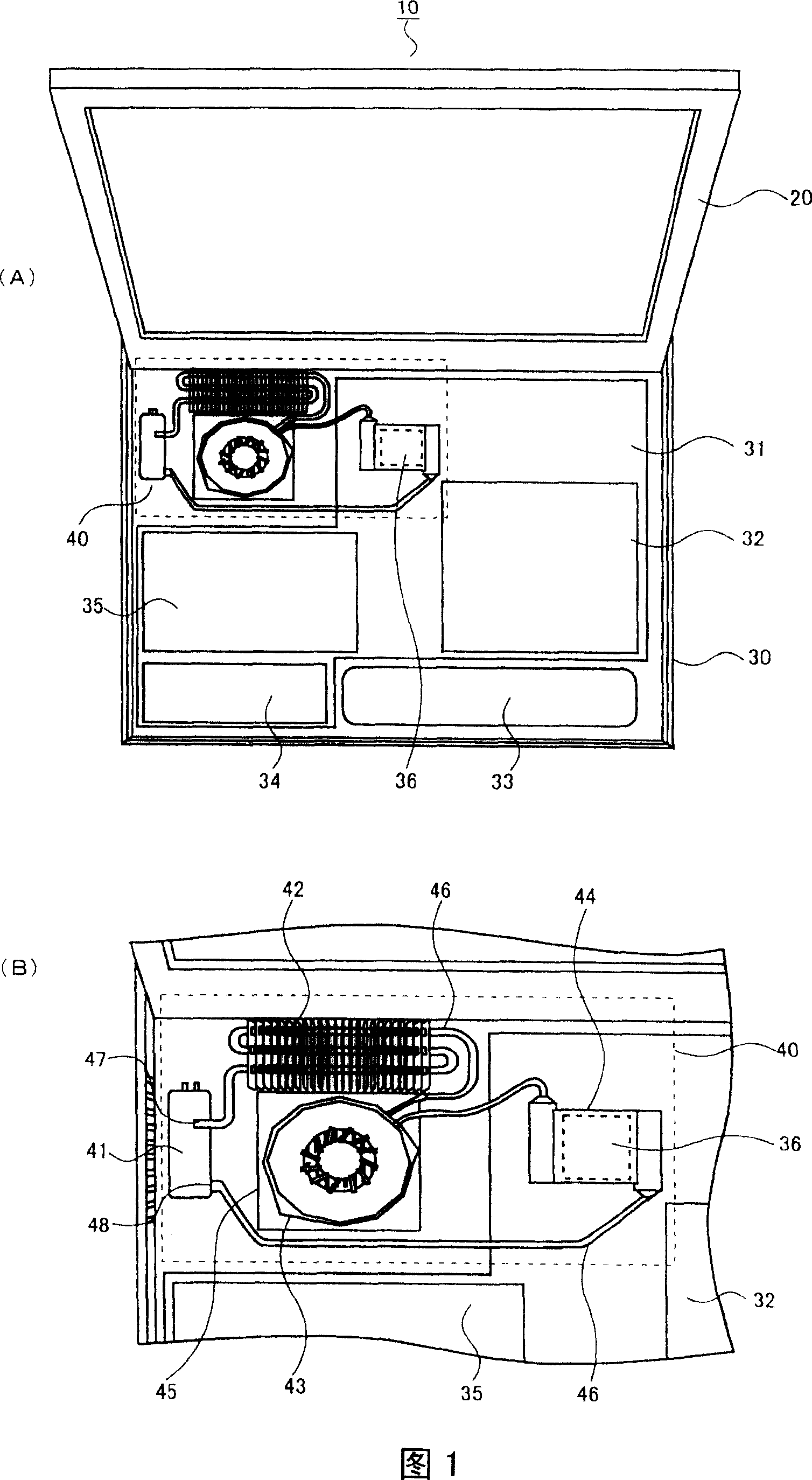
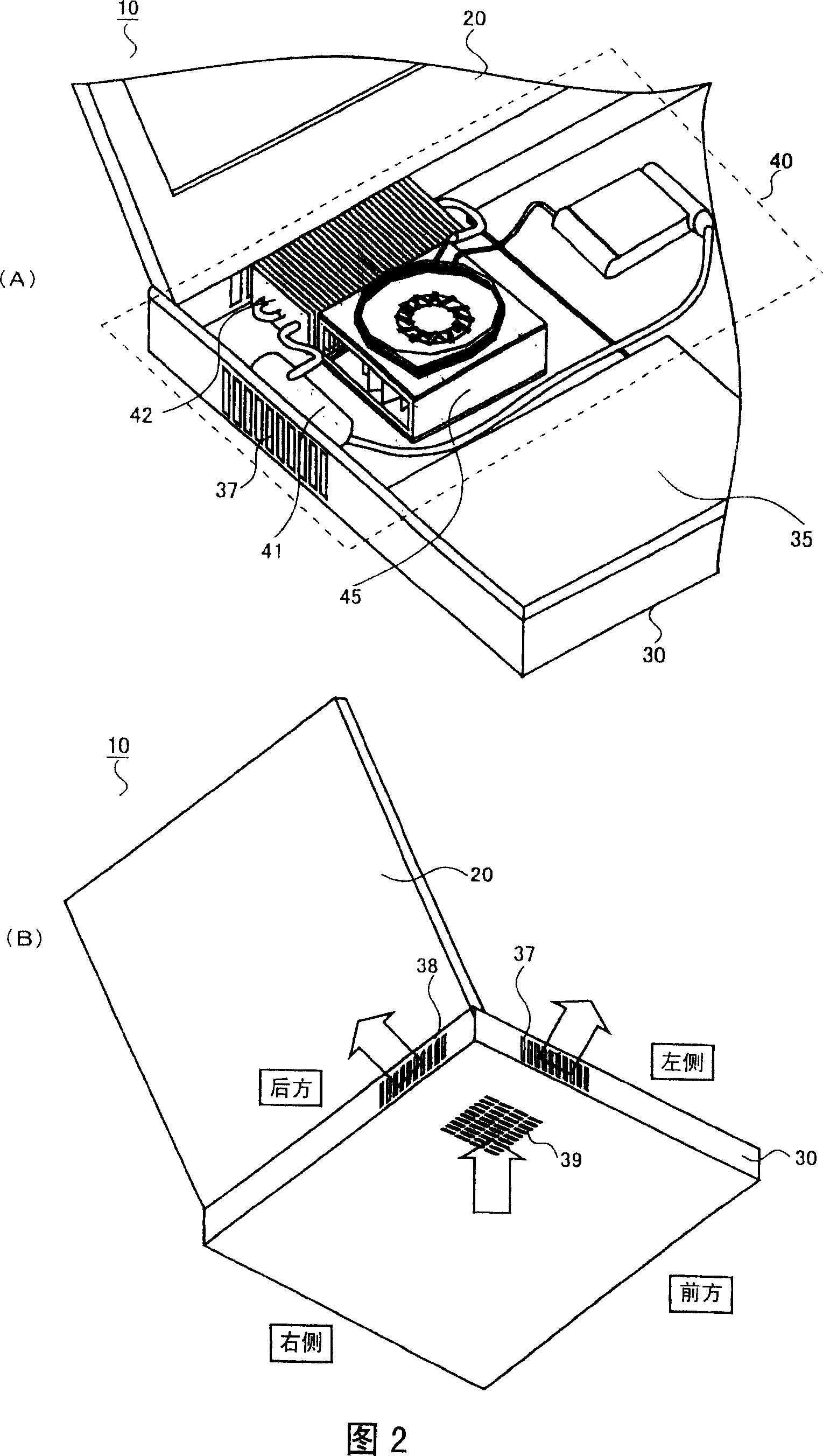
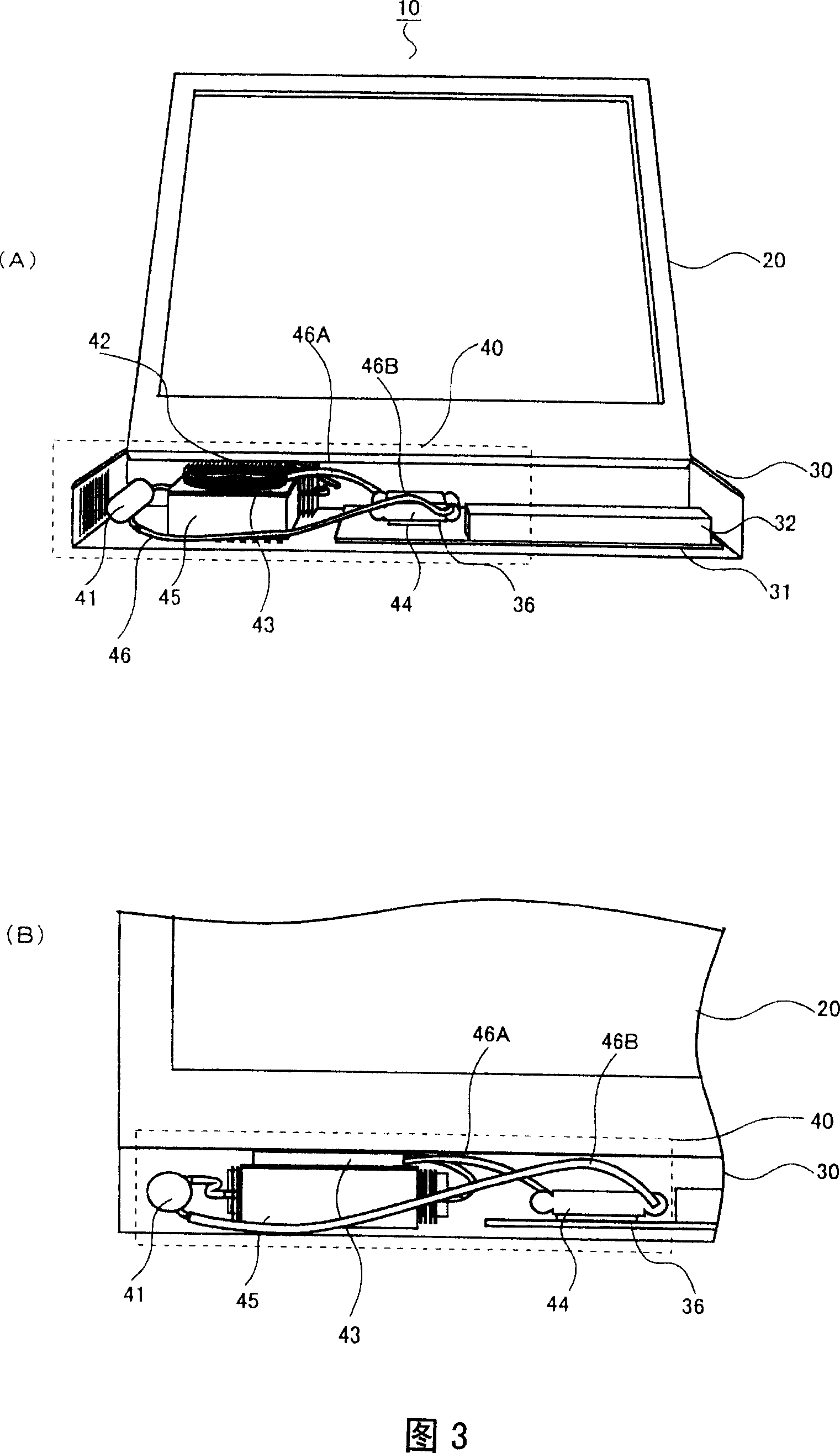
[0032] FIG. 1 is a diagram showing a notebook computer 10 (hereinafter simply referred to as a computer) according to this embodiment. 1(A) is a plan view of the computer 10 viewed from above, and FIG. 1(B) is a plan view showing a cooling device 40 built in the computer 10 .

[0033] Referring to FIG. 1(A), a computer 10 according to this embodiment includes a housing 30 incorporating functional elements such as a CPU 36 that generates heat, and a display unit 20 rotatably connected to the housing 30 .

[0034] The display unit 20 includes a display such as a liquid crys...


PUM


Abstract

A cooling device contained in a casing unit of a computer includes a compressor, a condenser, an evaporator, a capillary tube functioning as expanding means, and a blower fan. These components constituting the cooling device are connected to one another by tubular pipes. Moreover, in the present invention, the compressor, the condenser, and the blower fan are placed at two-dimensionally different positions, and longitudinal directions of the condenser and the compressor are placed in an L shape in a vicinity of the blower fan. With this configuration, a two-dimensional size of the cooling device can be made compact, so that the cooling device would not limit a layout of other components contained in the casing unit.

Description

technical field [0001] The present invention relates to a cooling device for electronic equipment and electronic equipment, and more particularly to a cooling device for electronic equipment using a refrigeration cycle and electronic equipment. Background technique [0002] In recent years, notebook computers have been remarkably improved in terms of their functionality and miniaturization. With the increase in functionality of notebook computers, CPUs (Central Processing Units) are developing at higher speeds and more functions, which increases the amount of heat emitted from the CPUs. [0003] In view of this, conventionally, in order to suppress the temperature rise of the CPU, a heat sink having good heat dissipation properties is attached to the surface of the CPU, and air is blown to the heat sink by a rotating blower fan. Furthermore, after heat transfer is performed using a heat pipe, heat dissipation of the heat sink is performed. By taking such measures, for exam...

Claims


Application Information

Patent Timeline
Patent Type & Authority Applications(China)
IPC IPC(8): H01L23/467G06F1/20
CPCG06F1/206H01L2924/0002F25B1/04G06F2200/201G06F1/203F25D23/006H01L2924/00G06F1/20H05K7/20
Inventor 土屋正树中村隆广
Owner SANYO ELECTRIC CO LTD
Why Eureka
Try Eureka