Measurement stand for holding a measuring instrument

A technology of measuring instruments and measuring racks, which is applied in the direction of measuring instrument components, instruments, measuring devices, etc., to achieve the effect of improving precise start-up, realizing mechanical and highly precise control

Inactive Publication Date: 2007-04-11
IMMOBILIENGESELLSCHAFT HELMUT FISCHER GMBH & CO KG
View PDF0 Cites 8 Cited by
  • Summary
  • Abstract
  • Description
  • Claims
  • Application Information

AI Technical Summary

Problems solved by technology

As a result, it is possible to detect falsified measurement data due to incorrect processing

Method used


Image

  • Measurement stand for holding a measuring instrument
  • Measurement stand for holding a measuring instrument
  • Measurement stand for holding a measuring instrument

Examples


Embodiment Construction

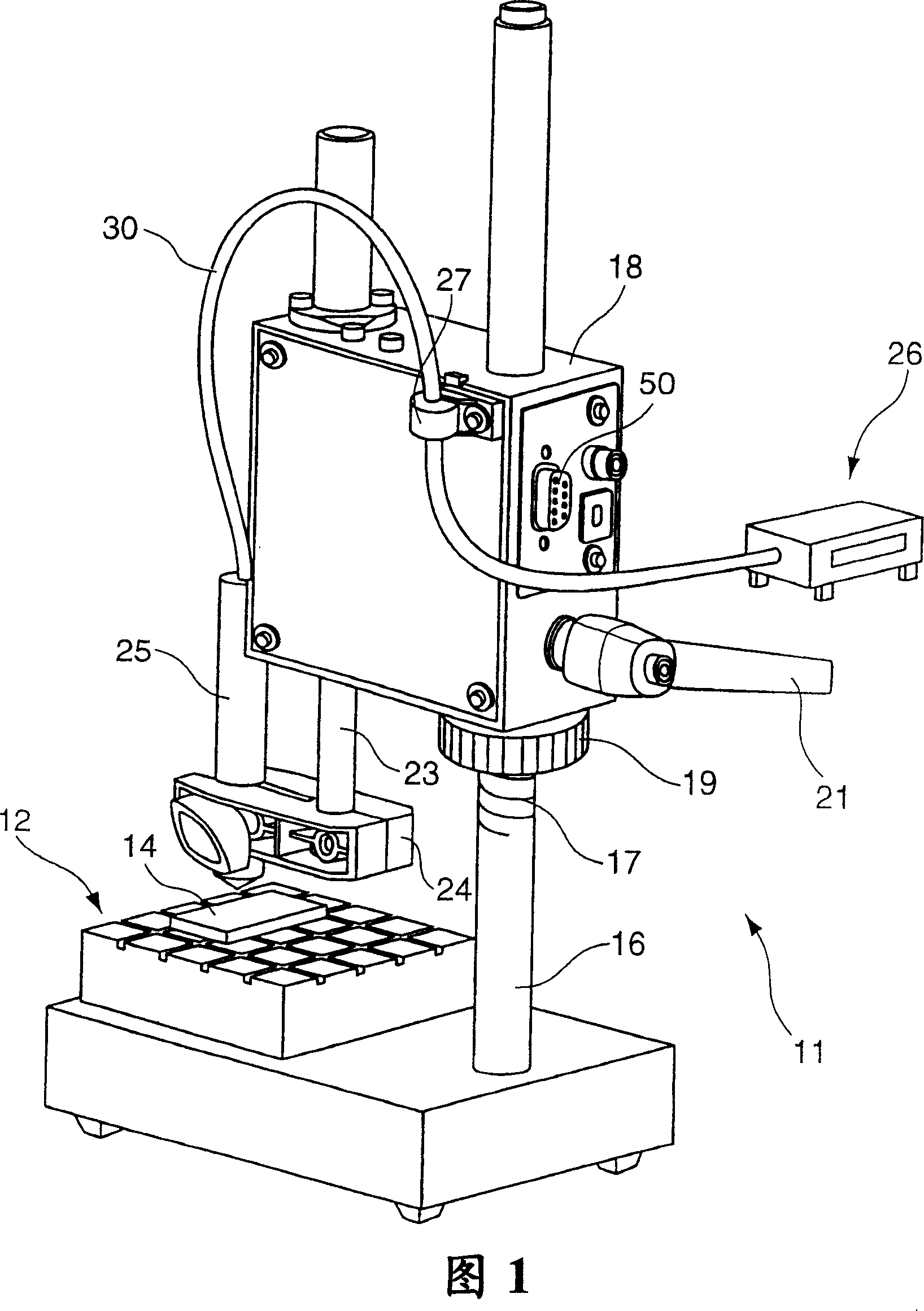
[0037] Figure 1 shows a measuring stand 11 according to the invention. Such a measuring stand 11 comprises a measuring table 12 on which individual measuring objects 14 can be positioned and placed. In the example shown, a magnetic slide is shown that accepts the object to be measured. The vertical column 16 holding the casing 18 is arranged on the bottom of the measuring frame 11 or on the measuring platform 12 , and the casing 18 can be adjusted vertically through the thread 17 . The height of the housing 18 can be precisely adjusted by adjusting the screw 19 and the clamping mechanism 21 .

[0038] The housing 18 accommodates the cam follower 23 so that the cam follower 23 can move up and down. A holding device 24 for detachably fixing a measuring instrument 26 is provided at the lower end of the cam follower 23 . The measuring device 26 comprises a measuring probe 25 for measuring the thickness of the thin layer. Such a measuring probe 25 can be touched on the surface ...


PUM


Abstract

A measurement stand for holding a measuring device ( 26 ), in particular a measuring arrangement ( 26 ) for measuring the thickness of thin layers, said measurement stand comprising a housing ( 18 ) in which a cam follower ( 23 ) is guided such that it can be moved up and down and the measuring device ( 26 ) is arranged at that end of said housing ( 18 ) that faces the measuring object ( 14 ), wherein a drive unit ( 29 ) with an electric drive ( 28 ) drives the lifting movement of the cam follower ( 23 ), wherein said drive unit ( 29 ) initiates in the down movement at least one first movement phase with a rapid motion and at least one further movement phase of the cam follower ( 23 ) with a creep motion until the measuring device ( 26 ) touches down on the measuring object ( 14 ).

Description

technical field [0001] The invention relates to a measuring stand for holding measuring instruments, in particular for holding measuring instruments for measuring the thickness of thin layers, said measuring stand comprising a housing in which a cam follower is guided so as to move up and down, and The measuring instrument is arranged at the end of the housing facing the measuring object. Background technique [0002] Such a measuring stand can be used, for example, to measure layer thicknesses. To measure the thickness of thin layers, the measuring object can be positioned on the measuring table of the measuring stand. The measuring instrument is provided at that end of the cam follower facing the measuring object, wherein the cam follower can be moved up and down. The up and down of the cam follower must be actuated by manually cranking the handle. [0003] By using a magnetic induction method or an eddy current method, the layer thickness can be measured. Which method...

Claims


Application Information

Patent Timeline
Patent Type & Authority Applications(China)
IPC IPC(8): G01D11/00G01B7/06
CPCG01B7/105G01B5/0004G01B3/008G01B5/0002G01B5/06
Inventor H·费希尔
Owner IMMOBILIENGESELLSCHAFT HELMUT FISCHER GMBH & CO KG
Why Eureka
Try Eureka