Vacuum deposition method and sealed-type evaporation source apparatus for vacuum deposition
A vacuum deposition and sealing technology, which is applied in vacuum evaporation plating, chemical instruments and methods, and from condensed steam, etc., can solve the problems that the temperature of the evaporation material does not increase, it is difficult to fill the evaporation material, and it is not easy to operate the sealed evaporation source. , to improve the yield
- Summary
- Abstract
- Description
- Claims
- Application Information
AI Technical Summary
Problems solved by technology
Method used
Image
Examples
Embodiment approach 1
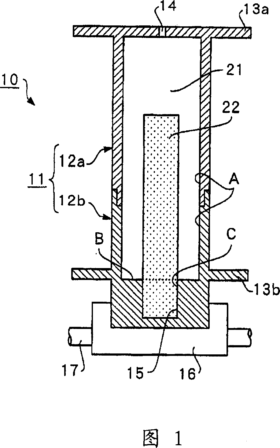
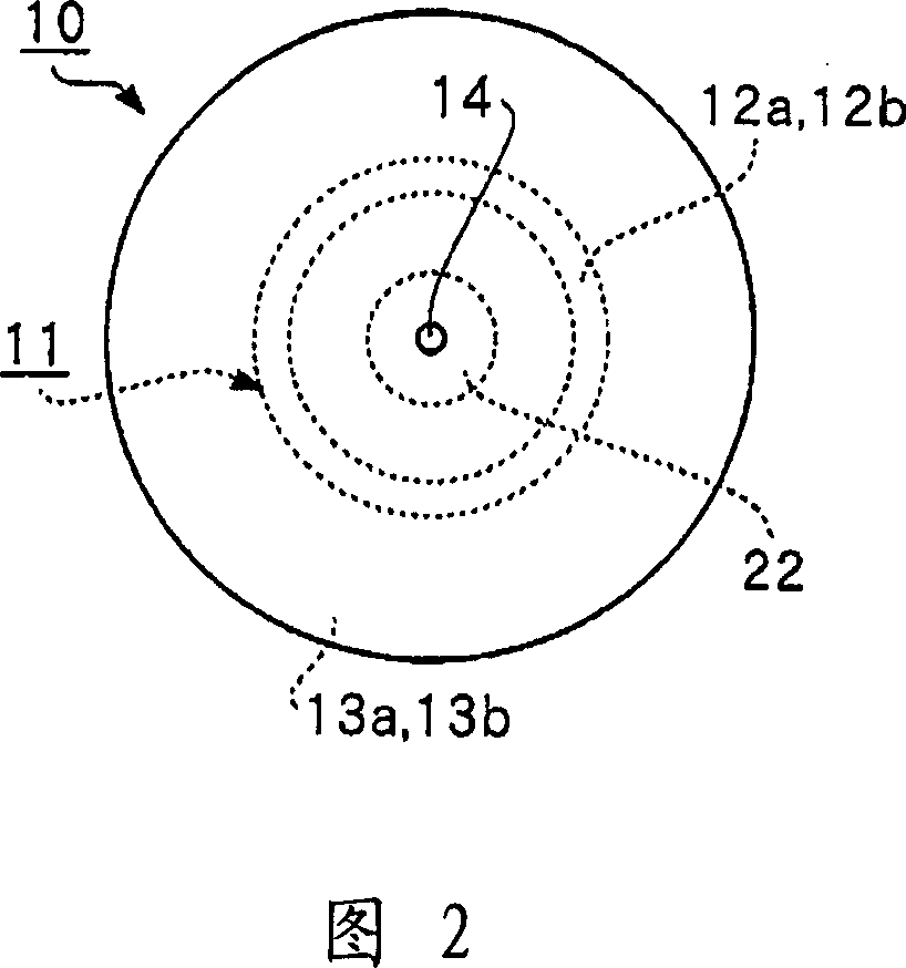
[0083] Currently, when depositing, for example, a SiO (evaporation material) protective film on the surface of spectacle lenses, many lenses are arranged on the upper part of the vacuum chamber and an open type evaporation source is provided on the lower part thereof. Generally, the protective film is deposited on the lens surface by a resistive heater. In this case, the deposited lens is manually replaced with a new lens. Additionally, the evaporative material is manually refilled. There are many other labors for exchanging the substrate or the spectacle lens which is the substrate to be deposited and for refilling the evaporated material.
[0084] As for SiO (or evaporation material), there are various materials such as powder particles or flakes of several millimeters, precision-formed materials called targets, materials of irregular size or shape, and others. These evaporation materials are generally marketed by manufacturers. Apart from specific manufacturers, shaped a...
Embodiment approach 2
[0106] The second embodiment relates to a vacuum deposition method as shown in FIGS. 5-9 and a sealed type evaporation source device corresponding to the vacuum deposition method. This embodiment can be practically applied to the case of continuously producing a gas barrier film of sufficient length. Thus, for example, SiO is deposited by supplying oxygen gas while spraying SiO onto a synthetic resin film such as a polyester film.
[0107] 5 is a longitudinal sectional side view conceptually illustrating a schematic configuration of a sealed type evaporation source device for vacuum deposition according to a second embodiment of the present invention. Fig. 6 is a longitudinal sectional side view conceptually illustrating the state of the sealed evaporation source device shown in Fig. 5 after operating for a period of time. FIG. 7 is a schematic illustration of a cross-sectional view of a portion taken along line 7-7 in FIG. 6. FIG.
[0108] In each configuration of FIGS. 5-7...
Embodiment approach 3
[0120] The third embodiment corresponds to a variation of heating the container in the second embodiment.
[0121] 8 is a longitudinal sectional side view conceptually illustrating a schematic configuration of a sealed type evaporation source device for vacuum deposition according to a third embodiment. Fig. 9 is a longitudinal sectional view conceptually illustrating a modification of the sealed type evaporation source device.
[0122] In the sealed type evaporation source device 70 shown in FIG. 8, the heating container 71 has a straight cylindrical body, unlike the tapered container shown in the second embodiment. The heating vessel 71 is composed of an upper heating cylinder 72a and a lower heating cylinder 72b which can be divided vertically. Other constituent elements are the same as those in Embodiment Mode 2. In this case, the same numerals are assigned to the common constituent elements shown in FIGS. 8 and 9 .
[0123] In the sealed type evaporation source of the ...
PUM
| Property | Measurement | Unit |
|---|---|---|
| surface area | aaaaa | aaaaa |
| diameter | aaaaa | aaaaa |
Abstract
Description
Claims
Application Information
 - R&D
- Intellectual Property
- Life Sciences
- Materials
- Tech Scout
- Unparalleled Data Quality
- Higher Quality Content
- 60% Fewer Hallucinations
Browse by: Latest US Patents, China's latest patents, Technical Efficacy Thesaurus, Application Domain, Technology Topic, Popular Technical Reports.
© 2025 PatSnap. All rights reserved.Legal|Privacy policy|Modern Slavery Act Transparency Statement|Sitemap|About US| Contact US: help@patsnap.com


