
Thermal vacuum deposition method and device

A technology of thermal vacuum and deposition equipment, which is applied in the direction of vacuum evaporation plating, ion implantation plating, metal material coating process, etc., and can solve the problems of substrate damage, a lot of time and cost of baseband, and unusable substrates. Achieve the effect of reducing space requirements

Inactive Publication Date: 2010-05-26
冯·阿德纳设备有限公司
View PDF4 Cites 0 Cited by
  • Summary
  • Abstract
  • Description
  • Claims
  • Application Information

AI Technical Summary

Problems solved by technology

If any transport failure occurs, such as a reduction in the transport speed of the substrate in the vaporization channel or a stop at the uniform surface temperature of the vaporization channel, the substrate can be damaged by overheating, thereby changing its physical properties to such an extent that the substrate cannot extent of use
In particular, due to the usual system size and special processing conditions, the cracking of the base tape involves a lot of time and cost required for repair

Method used


Image

  • Thermal vacuum deposition method and device
  • Thermal vacuum deposition method and device
  • Thermal vacuum deposition method and device

Examples


Embodiment Construction

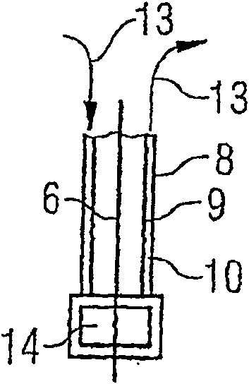
[0030] figure 1 A deposition apparatus 1 according to the invention is shown with a vacuum chamber 2 and vaporization channels 3 provided therein. The vaporization channel 3 has a height of about 4 meters and is arranged at an intermediate level of the vacuum chamber 2 at a height of about 10 meters. The vaporization channel 3 has a tall, elongated, hollow cuboid shape, and is opened at the base at the top and bottom ends.

[0031]At an intermediate level of the vacuum chamber 2 and of the vaporization channel 3, in the operating position substantially horizontally aligned nozzles 5 are mounted on two opposite sides, namely on either side of the substrate, the nozzles The tube feeds its narrow end into the vaporization channel 3 . The other end of the spray pipe 5 is connected to an evaporation device for evaporating the coating material.

[0032] The tape-shaped substrate 6 is conveyed through the vacuum chamber 2 and the vaporization channel 3 . The substrate 6 is aligne...


PUM


Abstract

The invention relates to a thermal vacuum deposition device and method in which a band-shaped substrate is continuously conveyed in a vaporization channel that is charged with a vaporous coating material. The aim of the invention is to allow the substrate to be quickly protected against damage during the coating process in previously known deposition methods and devices. Said aim is achieved by the inventive method, which is characterized in that the vaporization channel is sealed by inserting at least one positionally adjustable hollow element into an outer space of the vaporization channel and an inner space of the vaporization channel when a minimum conveying speed is not attained or when the substrate is at a standstill such that the substrate is located in the inner space.

Description

technical field [0001] The present invention relates to a method and apparatus for thermal vacuum deposition of continuously conveyed substrates by evaporating solid and / or liquid coating materials and vapor-phase depositing vaporous coating materials onto the substrates, wherein the The substrate moves in a heated vaporization channel, which is provided in the vacuum chamber and connected to the evaporation device, and the vaporization device and the evaporation device are the main parts of the deposition device. Background technique [0002] Various deposition methods are known for performing physical vapor deposition (PVD) in a vacuum. The deposition systems used to carry out the deposition are differentiated according to systems utilizing static or continuous methods. Unlike static methods, in continuous methods the substrate is continuously transported through the deposition apparatus. Accordingly, the coating material is continuously supplied in the form of vapor to ...

Claims


Application Information

Patent Timeline
Patent Type & Authority Patents(China)
IPC IPC(8): C23C14/24C23C14/56
CPCC23C14/562C23C14/24C23C14/564
Inventor 卢茨·戈特斯曼乌尔夫·赛费特伯恩特-迪特尔·温泽尔莱茵哈德·耶格尔
Owner 冯·阿德纳设备有限公司
Learn More