Heat exchange plate for plate heat exchanger

A plate heat exchanger, heat exchange plate technology, applied in heat exchange equipment, lighting and heating equipment, laminated components, etc., can solve the problems of difficult assembly and operation, many molds, etc., to reduce equipment investment and improve heat transfer coefficient. , the effect of improving the heat transfer coefficient

Active Publication Date: 2007-04-25
SHANDONG BEICHEN MECHANICAL & ELECTRICAL EQUIP
View PDF0 Cites 5 Cited by
  • Summary
  • Abstract
  • Description
  • Claims
  • Application Information

AI Technical Summary

Problems solved by technology

[0002] The plate heat exchanger is a high-efficiency heat exchange equipment with a metal corrugated plate as the heat transfer element. The corrugations in the heat exchange plate adopt a symmetrical design, that is, the angles of the corrugations on both sides of the center line of the same plate are the same, so althou

Method used


Image

  • Heat exchange plate for plate heat exchanger

Examples


Embodiment 1

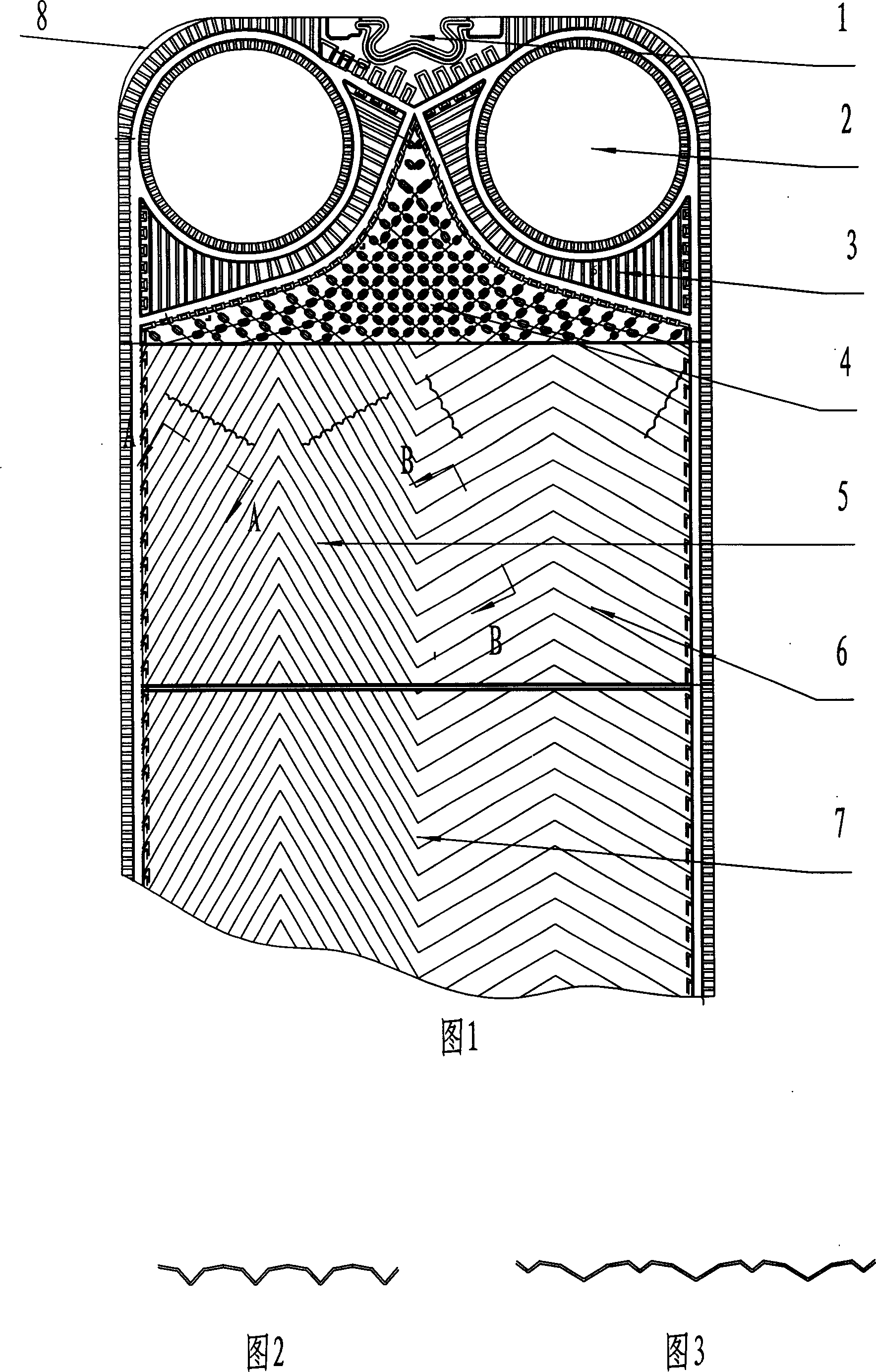
[0015] Embodiment 1, a heat exchange plate of a plate heat exchanger, made of pressed stainless steel plate, including positioning hole 1, medium inlet and outlet 2, inlet and outlet diversion area 3, diversion area 4, heat transfer area, its structure is: The plate corrugation in the heat transfer zone is divided into two sides by the center line of the plate, and the obtuse-angle corrugation 7 on one side is connected to the acute-angle corrugation 6 on the other side.

Embodiment 2

[0016] Embodiment 2, a heat exchange plate of a plate heat exchanger, made of pressed stainless steel plate, including positioning hole 1, medium inlet and outlet 2, inlet and outlet diversion area 3, diversion area 4, heat transfer area, its structure is: The plate corrugation in the heat transfer zone is divided into two sides by the center line of the plate, one side is a 120° obtuse angle corrugation 7 connected to the other side 60° acute angle corrugation 6, and a reinforcing rib is added between the two corrugations.

Embodiment 3

[0017] Embodiment 3, a heat exchange plate of a plate heat exchanger, made of pressed stainless steel plate, including positioning hole 1, medium inlet and outlet 2, inlet and outlet diversion area 3, diversion area 4, and heat transfer area, its structure is: The plate corrugation in the heat transfer zone is divided into two sides by the center line of the plate, one side is a 120 ° obtuse angle corrugation 7 connected to the other side 60 ° acute angle corrugation 6, and a reinforcing rib is added between the two corrugations; The diameter ratio of the corrugated channels on both sides of the plate is 1:2.2; the four corners of the heat exchange plate are provided with corner locking pieces 8 .


PUM


Abstract

The invention discloses a heat exchanging plate of plate type heat exchanger, belonging to the parts of heat exchanging equipment with no directly contacting heat exchanging medium, especially the parts of heat exchanging equipment which is used for fixed plate or laminating channel of two exchanging mediums and in which each medium is not contacted with different side face of the channel. The heat exchanging plate comprises locating hole, in-off hole of medium, guiding region of in-off hole, diverge region, and heat conducting region. It is characterized in that plate ripple in the heat conduction region is divided into two sides by the plate central line, one side is ripple with blunt angle and the other side is ripple with acute angle. The benefit of invention is because ripples with different angle are applied in the plate by the plate central line, the flux of heat exchanging amount is matched with permitted pressure-drop better. Meanwhile, because the path diameter ratio of ripples on two sides of heat exchanging plate is different, velocity of flow of cool and heat medium is approach or equal among plates and the heat exchanging coefficient is improved by 5-10%. The invention is applied in the update of original production.

Description

technical field [0001] The invention belongs to parts of heat exchange devices in which the heat exchange media are not in direct contact, in particular to fixed plates or laminated channels for two exchange media, parts of heat exchange devices in which the media are in contact with different sides of the channels . Background technique [0002] The plate heat exchanger is a high-efficiency heat exchange equipment with a metal corrugated plate as the heat transfer element. The corrugations in the heat exchange plate adopt a symmetrical design, that is, the angles of the corrugations on both sides of the center line of the same plate are the same, so although the manufacturing process is simple , but in the usual heat exchange state, the flow rate of the hot medium and the cold medium are different, and two kinds of plates with different angles are used to cross each other for assembly. Many molds are needed in the manufacture, and it is not easy to operate in the assembly. ...

Claims


Application Information

Patent Timeline
IPC IPC(8): F28F3/04
Inventor 唐金山
Owner SHANDONG BEICHEN MECHANICAL & ELECTRICAL EQUIP
Why Eureka
Try Eureka