Automatic collimating method and collimator set for light path of colidar

A laser radar and automatic collimation technology, applied in the laser field, can solve the problems of cumbersome and time-consuming, invalid measurement signal, optical axis deviation, etc., and achieve the effect of practical operation, simple overall structure and advanced mechanical structure.

Inactive Publication Date: 2007-04-25
ANHUI INST OF OPTICS & FINE MECHANICS - CHINESE ACAD OF SCI
View PDF0 Cites 26 Cited by
  • Summary
  • Abstract
  • Description
  • Claims
  • Application Information

AI Technical Summary

Problems solved by technology

However, due to temperature changes, optical platform vibrations, laser mode changes or wavelength replacements, etc., the optical axis of the laser radar receiving and transmitting systems often deviates. It is to strictly match the receiving field of view angle with the divergence angle of the emitting laser, because the deviation of the optical axis of the transceiver system will cause errors in the measurement signal, and this error can only be found when the measurement data is calculated and processed, thus resulting in a large number of measurements invalid signal
For non-coaxial lidar, the receiving and transmitting points are relatively far away, the beam quality is poor, and the horizontal emission will make the alignment of the optical path difficult; while the lidar system for Raman, polarization, and high-level detection of the middle layer of the stratosphere is Reducing the interference of sky background light often requires reducing the receiving field of view, which makes it more difficult to align the receiving and receiving light paths
[0004] This work has been manual operation in the past, which is cumbersome and time-consuming, with large errors, and requires professionally trained high-tech personnel to perform fine work with the help of precision optical adjustment brackets and leveling instruments

Method used


Image

  • Automatic collimating method and collimator set for light path of colidar
  • Automatic collimating method and collimator set for light path of colidar
  • Automatic collimating method and collimator set for light path of colidar

Examples


Embodiment Construction

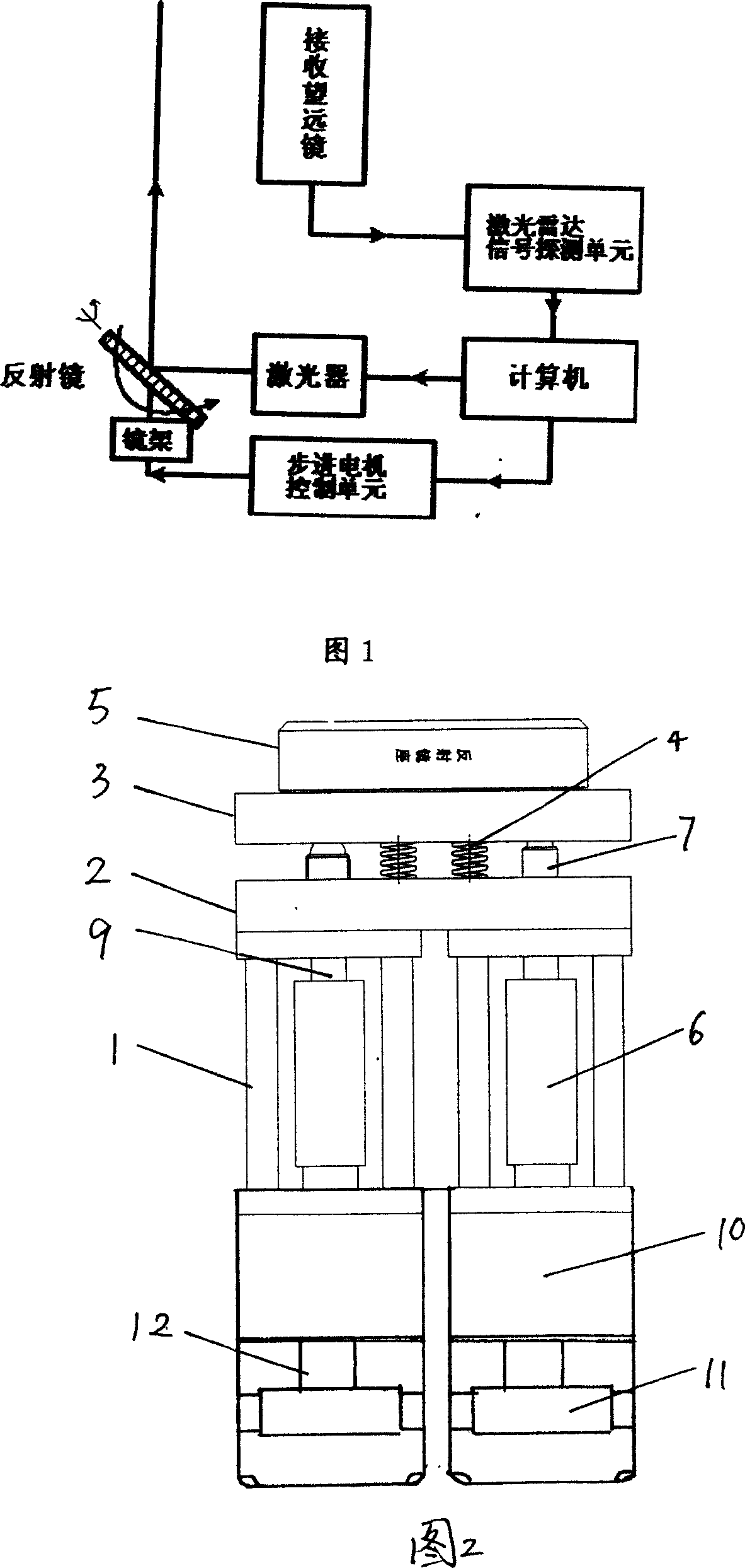
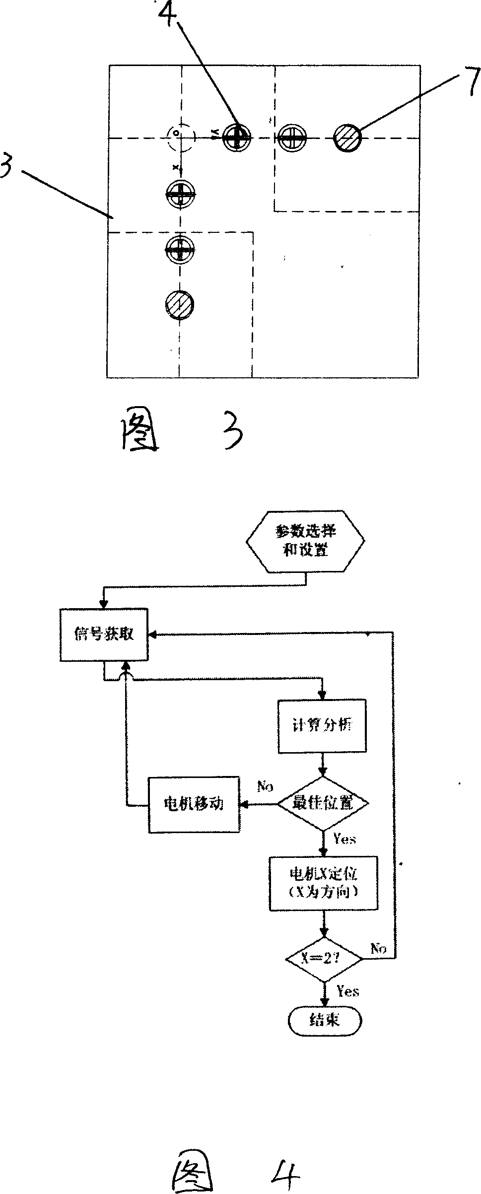
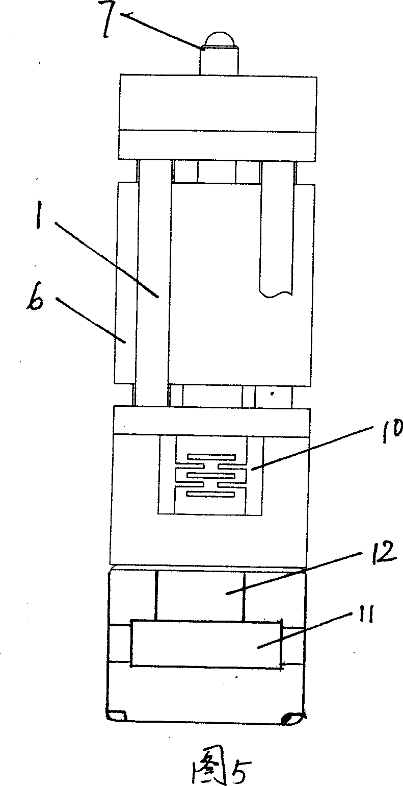
[0031] The lidar optical path automatic collimator includes reflectors, lasers, signal detection units, receiving telescopes and computers, and is characterized in that it includes a mirror frame 1, a fixed plate 2 is installed on the mirror frame, and a movable plate is installed on the fixed plate 2 3. The movable plate 3 and the fixed plate 2 are connected by a spring 4, the reflector 5 is installed on the movable plate 3, and two sets of sliders / micrometer head mechanisms and their driving stepping motors are installed in the mirror frame 1. There are ejector rods 7 at the upper ends of the two slide blocks 6 , which extend from the openings on the mirror frame 1 and the fixed plate 2 to below the movable plate 3 . The push rod 7 and the spring 4 are vertically distributed on the lower surface of the movable plate along the X-Y axis, and a steel ball 8 is installed between the fixed plate 2 and the movable plate 3 at the intersection of the X-Y axis.

[0032] The slider / mi...


PUM


Abstract

A laser radar optical path autocollimation method and collimator are disclosed that comprise reflector, laser, signal detecting element, receiving telescope and computer. It's characterized in that it includes mirror bracket, a fixed plate is mounted on the mirror bracket, a movable plate is mounted on the fixed plate, the fixed plate is connected with the movable plate via springs, the reflector is located on the movable plate, two sets of slide blocks/micrometer mechanism and driven step motor are mounted in the mirror bracket, there are push-rods on the slide blocks which extend from the hole on top of the bracket and the fixed plate to the underside of the movable plate. The slide blocks and the push-rods are motivated upwards by the rotation of the driven step motor, the movable plate is adjusted to rotate along the X, Y axis, and the target position of the reflector is fixed at last with high accuracy. The application prospect: atmosphere scientific experiment measuring apparatus and measuring means can be used in various laser radar systems.

Description

technical field [0001] The invention belongs to a laser technology, in particular to an automatic collimation method and an instrument of a laser radar light path. Background technique [0002] With the development of laser, optoelectronic technology and signal detection technology, lidar is more and more widely used in the fields of environmental monitoring and atmospheric science research. Lidar has gradually become a conventional observation tool, and as a conventional observation tool, the requirements for the stability and automation of lidar are getting higher and higher. [0003] In the lidar system, it is required to strictly match the receiving field of view with the divergence angle of the emitted laser. However, due to temperature changes, optical platform vibrations, laser mode changes or wavelength replacements, etc., the optical axis of the laser radar receiving and transmitting systems often deviates. It is to strictly match the receiving field of view angle...

Claims


Application Information

Patent Timeline
Patent Type & Authority Applications(China)
IPC IPC(8): G01S7/497G01S7/493G01S17/00G01C15/00
Inventor 李琛刘小勤胡顺星薛辉胡欢陵
Owner ANHUI INST OF OPTICS & FINE MECHANICS - CHINESE ACAD OF SCI
Why Eureka
Try Eureka