Load drive device, vehicle, and abnormality processing method in load drive device
A load driving and abnormal handling technology, applied in the arrangement of multiple different prime movers of power plants, hybrid vehicles, and general power plants, etc., can solve the problems of voltage rise, inability to suppress voltage increase, inability to prevent overvoltage, etc.
- Summary
- Abstract
- Description
- Claims
- Application Information
AI Technical Summary
Problems solved by technology
Method used
Image

Examples
no. 1 example
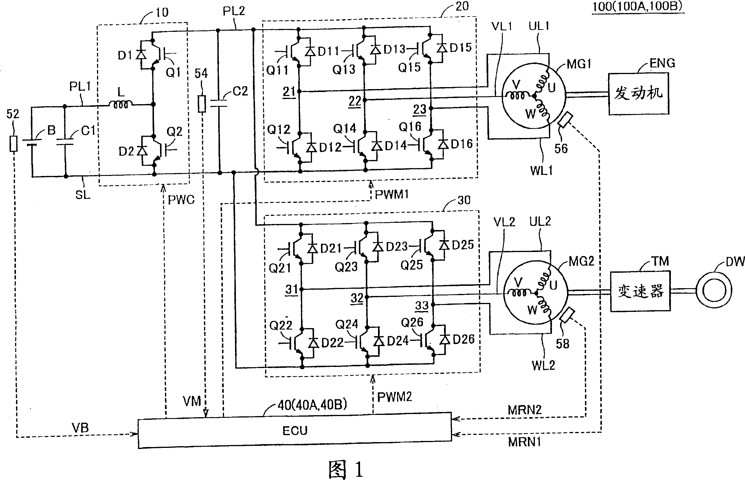
[0052] FIG. 1 is a functional block diagram of a hybrid vehicle considered as an example of a vehicle in which a load driving apparatus according to a first embodiment of the present invention is included. 1, the hybrid vehicle 100 includes a battery B, a booster 10, inverters 20 and 30, an ECU (Electronic Control Unit) 40, motor generators MG1 and MG2, an engine ENG, a transmission TM, drive wheels DW, Capacitors C1 and C2, voltage sensors 52 and 54, rotation speed sensors 56 and 58, power supply lines PL1 and PL2, ground line SL, U-phase lines UL1 and UL2, V-phase lines VL1 and VL2, and W-phase lines WL1 and WL2.
[0053] Motor generators MG1 and MG2 are rotary electric machines, and are composed of 3-phase AC (Alternating Current) synchronous motor generators. Motor generator MG1 generates a 3-phase AC voltage using the power of engine ENG to supply the generated 3-phase AC voltage to inverter 20 . Motor generator MG1 also generates driving force by the 3-phase AC voltage ...
no. 2 example
[0096] Even when excessive rotation of motor generator MG2 occurs and thus torque reduction control of motor generator MG2 is performed, if motor generator MG1 is currently stopped or in power supply operation, the voltage VM reflecting the torque reduction control of motor generator MG2 Increase will not occur. In the second embodiment, when over-rotation of motor generator MG2 occurs, the boosting ratio of booster 10 will be maintained without being reduced if motor generator MG1 is currently shutting down or in feed running operation. In the second embodiment, the limit value of the number of motor revolutions MRN2 for reducing the boosting ratio of the booster 10 is set lower than the limit value of the number of motor revolutions MRN2 for performing torque reduction control of the motor generator MG2. the above limit value. Thus, complete protection against inverter overvoltage is obtained.
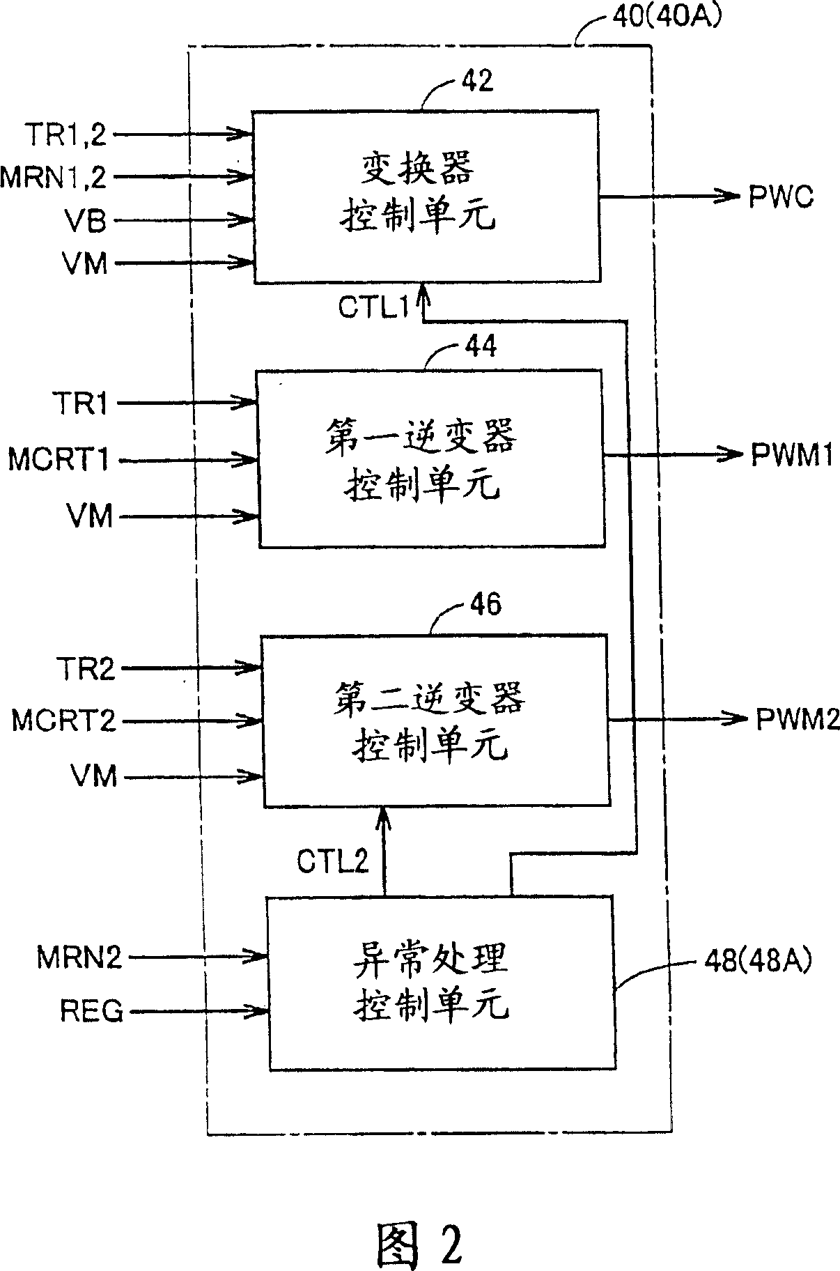
[0097] Referring again to FIGS. 1 and 2 . A hybrid vehicle 100A including the...
no. 3 example
[0110] Although the torque reduction control of the motor generator MG2 is performed in response to the excessive rotation of the motor generator MG2, in the case where the power consumption of the motor generator MG2 immediately before the performance of the torque reduction control is small, the torque of the motor generator MG2 is reflected The rise of the reduced voltage VM is smaller. In the third embodiment, when excessive rotation occurs to motor generator MG2, the boosting ratio of booster 10 is reduced only if the electric power consumed by motor generator MG2 exceeds a preset threshold.
[0111] A hybrid vehicle 100B including the load driving device of the third embodiment is based on the configuration of the hybrid vehicle 100 of the first embodiment shown in FIG. 1 , and includes an ECU 40B instead of the ECU 40 .
[0112] FIG. 7 is a functional block diagram of an ECU 40B according to a third embodiment of the present invention. Referring to FIG. 7 , an ECU 40B ...
PUM
 Abstract
Description
Claims
Application Information
 - R&D
- Intellectual Property
- Life Sciences
- Materials
- Tech Scout
- Unparalleled Data Quality
- Higher Quality Content
- 60% Fewer Hallucinations
Browse by: Latest US Patents, China's latest patents, Technical Efficacy Thesaurus, Application Domain, Technology Topic, Popular Technical Reports.
© 2025 PatSnap. All rights reserved.Legal|Privacy policy|Modern Slavery Act Transparency Statement|Sitemap|About US| Contact US: help@patsnap.com