Check patentability & draft patents in minutes with Patsnap Eureka AI!

Electrochemical machining method in cellular dimple structure

A processing method and honeycomb technology, applied in the direction of electric processing equipment, electrochemical processing equipment, processing electrodes, etc., can solve the problems of poor surface quality, high manufacturing cost, and low efficiency

Inactive Publication Date: 2007-05-09
NANJING UNIV OF AERONAUTICS & ASTRONAUTICS
View PDF0 Cites 33 Cited by
  • Summary
  • Abstract
  • Description
  • Claims
  • Application Information

AI Technical Summary

Problems solved by technology

[0005] The purpose of the present invention is to solve the common defects of low efficiency, low surface quality and high manufacturing cost in the processing of honeycomb micropit structures, and provide a honeycomb micropit with high production efficiency, high surface quality and low manufacturing cost. pit structure electrolytic machining method

Method used


Image

  • Electrochemical machining method in cellular dimple structure
  • Electrochemical machining method in cellular dimple structure

Examples


Embodiment Construction

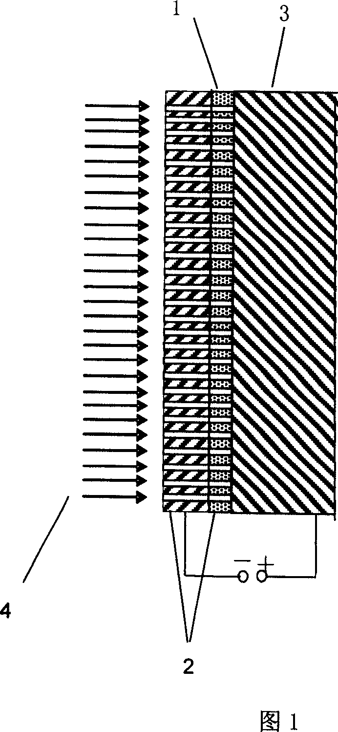
[0013] As shown in Figure 1, the electrolytic machining process of the honeycomb micropit structure. The surface of the tool cathode 2 has a shielding film 1, while the anode 3 does not need any such steps, and it can be electrolytically processed after the tool cathode 2 clamps it. The electrolyte 4 is sprayed to the surface of the tool cathode under the action of the pump, and reaches the area of ​​the tool cathode and the workpiece anode through the inner cavity of the cathode fixture. At this time, the group hole structure is not only the solution inflow channel, but also the solution outflow channel, and the electrolyte Then enter the outflow channel through the flow channel of the cathode holder.

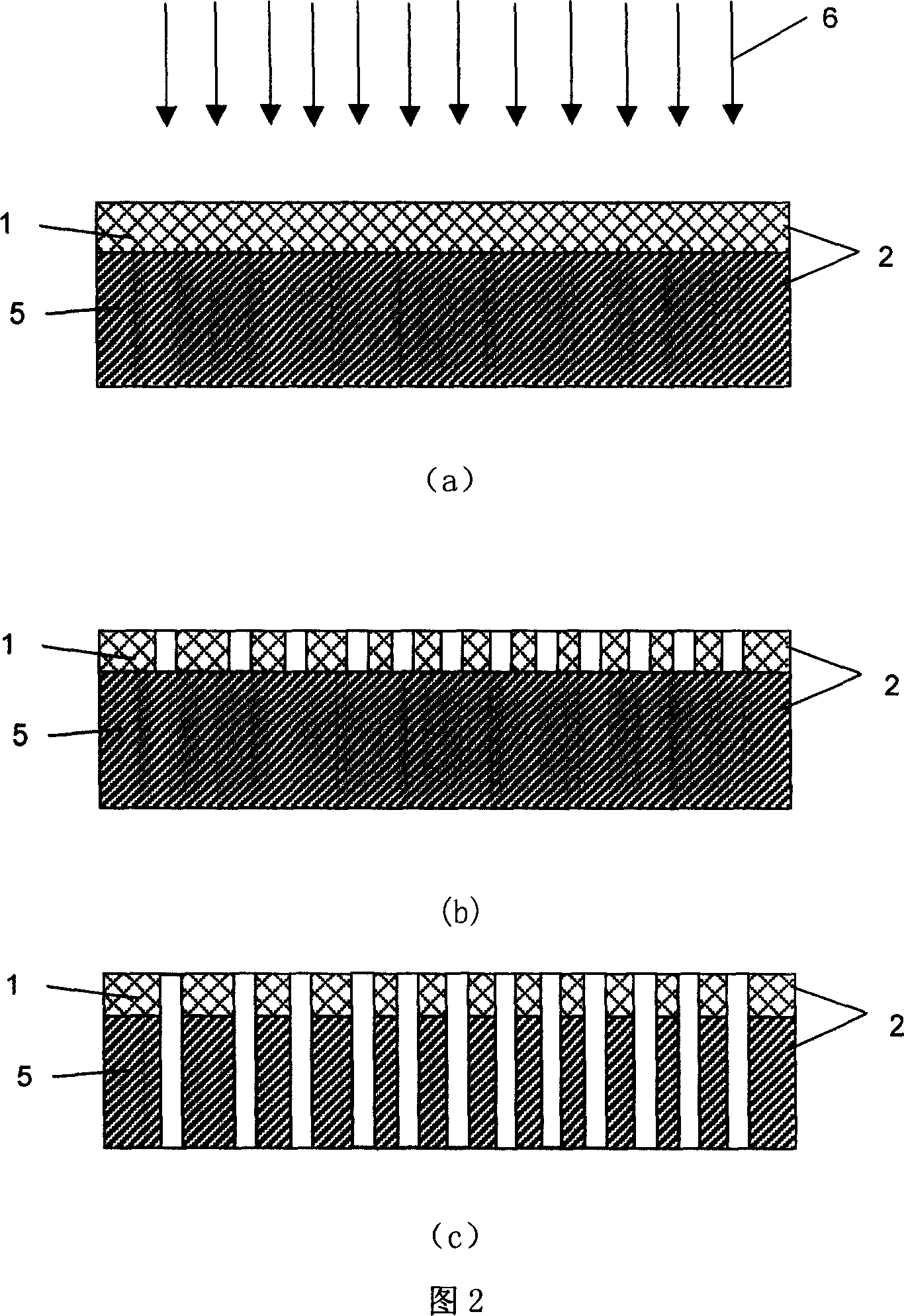
[0014] Figure 2 is a schematic diagram of the tool cathode manufacturing process. The shielding film 1 is coated on the substrate 5, and the pattern shown in Figure 2(b) is formed after photolithography and development. The exposed part of the substrate can be etched. Physica...


PUM


Abstract

An electrolyzing method for preparing the cellular micropits structure includes such steps as making a tool as cathode with a group of through holes and a shielding film on its surface, uniformly spraying the electrolyte through said through holes onto a workpiece as anode, and electrolyzing.

Description

technical field [0001] The electrolytic machining method of the honeycomb micropit structure of the invention belongs to the technical field of electrolytic machining. Background technique [0002] Electrolytic machining is a special processing technology, which is a processing method that uses the principle of electrochemical anodic dissolution to remove materials. It has the outstanding advantages of fast processing speed, good surface quality, no loss of tools, no restrictions on material strength, toughness, hardness, etc., and no macro cutting force. It has been widely used in aerospace, weapons, automobiles, molds and other industries. . [0003] The surface structure with honeycomb micropit is widely used in the inner surface of the engine cylinder as a way to improve the sliding friction. Its manufacturing method usually adopts four kinds of micropit processing methods commonly used at present: ① self-excited vibration processing method. In the case that the workin...

Claims


Application Information

Patent Timeline
IPC IPC(8): B23H3/00B23H3/04
Inventor 朱荻曲宁松王光强李冬林
Owner NANJING UNIV OF AERONAUTICS & ASTRONAUTICS
Features
  • R&D
  • Intellectual Property
  • Life Sciences
  • Materials
  • Tech Scout
  • Unparalleled Data Quality
  • Higher Quality Content
  • 60% Fewer Hallucinations
Learn More