Speed adjustment control system of steam turbine

A control system, steam turbine technology, applied in mechanical equipment, engine components, machines/engines, etc.

Inactive Publication Date: 2007-05-09
沈阳创思达自动化系统有限公司
View PDF0 Cites 22 Cited by
  • Summary
  • Abstract
  • Description
  • Claims
  • Application Information

AI Technical Summary

Problems solved by technology

At present, the electromagnetic drive mechanism cannot meet this special requirement, so the steam turbine regulation and protectio

Method used


Image

  • Speed adjustment control system of steam turbine
  • Speed adjustment control system of steam turbine
  • Speed adjustment control system of steam turbine

Examples


Embodiment Construction

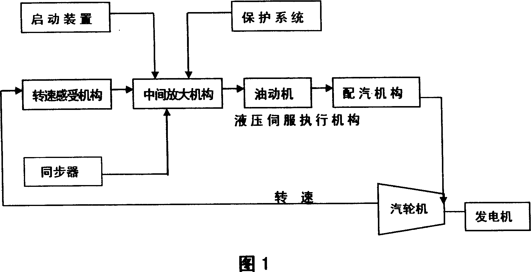
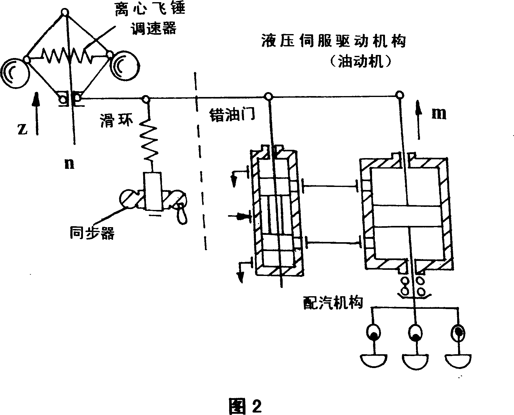
[0016] As shown in the figure, the speed control system of the steam turbine includes: a speed sensing mechanism, an intermediate amplification mechanism, a synchronizer, a starting device, an oil motor, and a steam distribution mechanism; the speed sensing mechanism receives the speed signal of the steam turbine rotor and Transform into a primary control signal; the intermediate amplifier amplifies the power of the primary control signal sent by the speed sensing mechanism, and performs control calculations according to the adjustment target; the oil motor generates the driving force to drive the steam distribution mechanism according to the control signal of the intermediate amplifier , and reach the predetermined opening position; the steam distribution mechanism converts the stroke of the oil motor into the opening of each regulating valve, so that the steam intake of the steam turbine and the stroke of the oil motor are corrected to an approximately linear relationship; the...


PUM


Abstract

A speed controlling device of steam turbine consists of rotation speed sensing mechanism, intermediate amplifying mechanism, synchronizer, start-up unit, oil supplier and valve actuating mechanism. It is featured as calibrating relation of air intake flow on steam turbine to stroke of oil supplier to be approximately linear relation, utilizing synchronizer to act on intermediate amplifier to generate control signal for controlling stroke of oil supplier so as to change rotary speed of steam turbine.

Description

technical field [0001] The invention belongs to the field of steam turbine control, in particular to a speed control system of a steam turbine. Background technique [0002] The task of the steam turbine speed control system is: during normal operation, by changing the steam intake of the steam turbine, the power output of the steam turbine meets the external load requirements, and the adjusted speed deviation is within the allowable range; Next, quickly close the regulating valve or the main valve to keep the unit idling or stop quickly. Relying on the self-regulating operation of the steam turbine will definitely cause large fluctuations in the speed of the steam turbine, which cannot meet the requirements of operation. In this way, there must be a speed control system, which can be adjusted by the signal of the change of the speed of the steam turbine. [0003] Due to the high steam pressure of the steam turbine, a large driving force is required to open the main steam ...

Claims


Application Information

Patent Timeline
IPC IPC(8): F01D17/26F01D17/10
Inventor 兰国强
Owner 沈阳创思达自动化系统有限公司
Why Eureka
Try Eureka