
Method and device for preventing grain defect of wafer in use for vacuum system

A vacuum system and particle defect technology, applied in the direction of valve devices, electrical components, engine components, etc., can solve irreparable losses, affect the working time of the machine and other problems, and achieve the effect of ensuring continuous operation

Inactive Publication Date: 2007-05-09
SEMICON MFG INT (SHANGHAI) CORP +1
View PDF0 Cites 5 Cited by
  • Summary
  • Abstract
  • Description
  • Claims
  • Application Information

AI Technical Summary

Problems solved by technology

This will affect the working time of the machine and cannot recover the losses that have been caused

Method used


Image

  • Method and device for preventing grain defect of wafer in use for vacuum system
  • Method and device for preventing grain defect of wafer in use for vacuum system
  • Method and device for preventing grain defect of wafer in use for vacuum system

Examples


Embodiment Construction

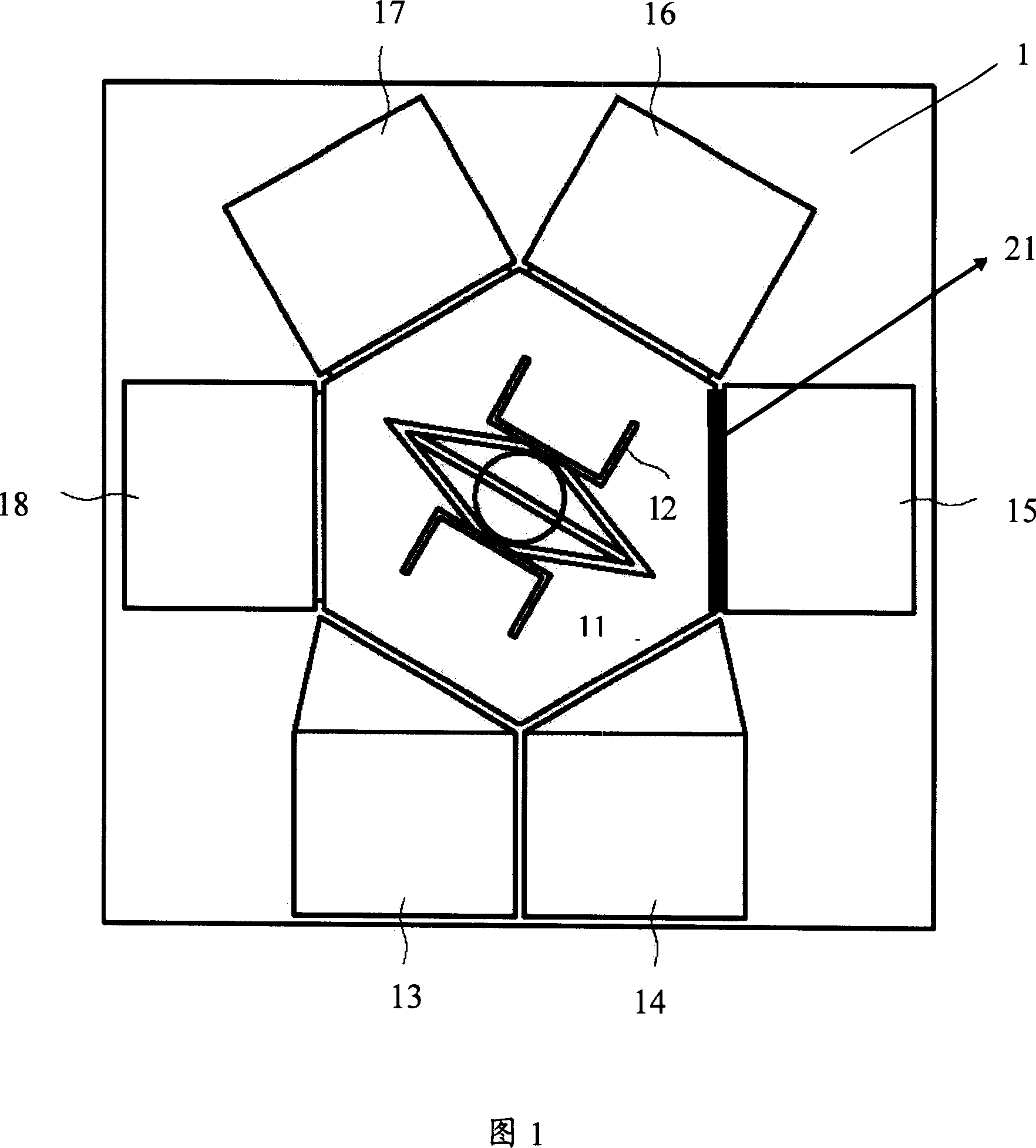
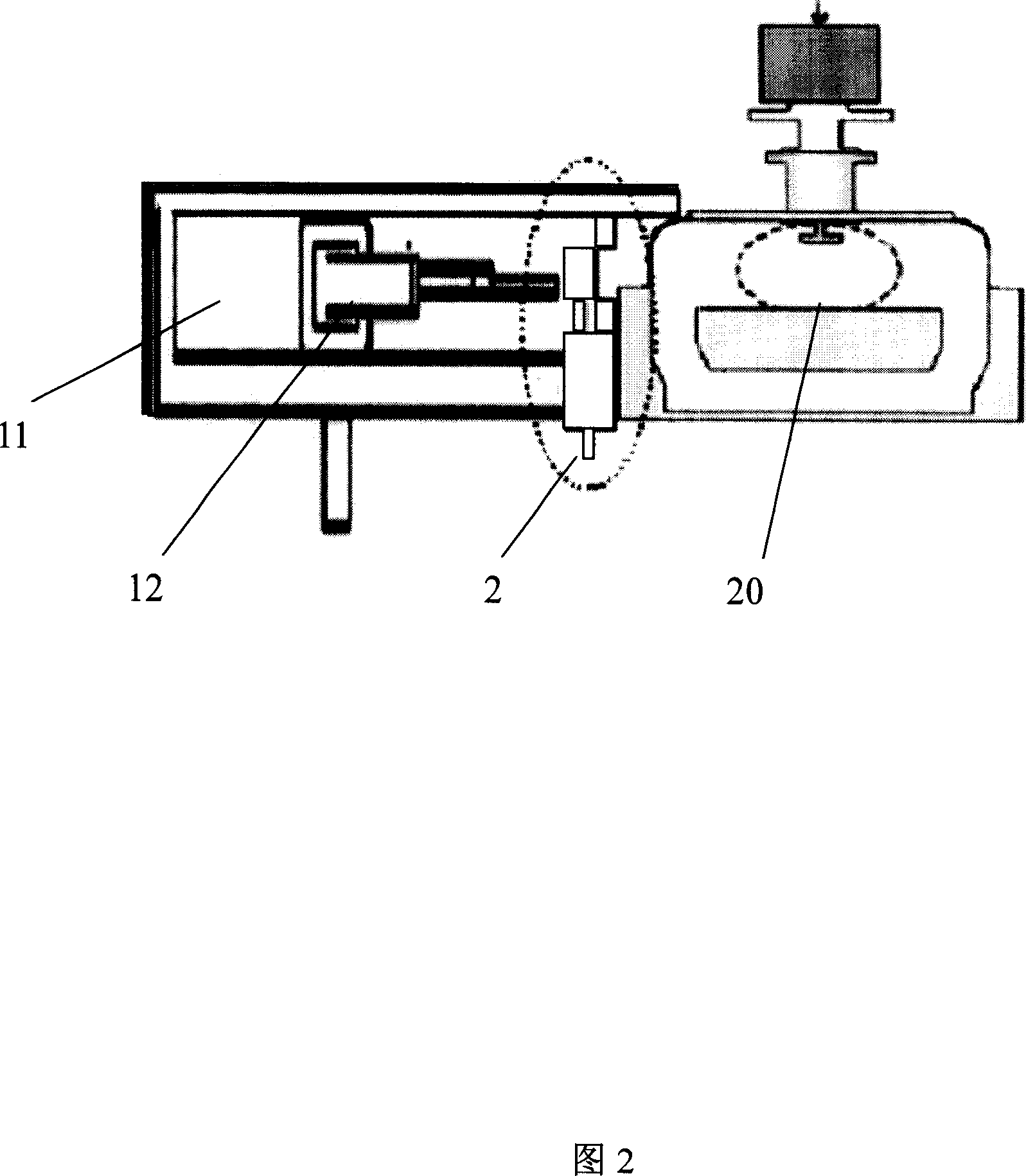
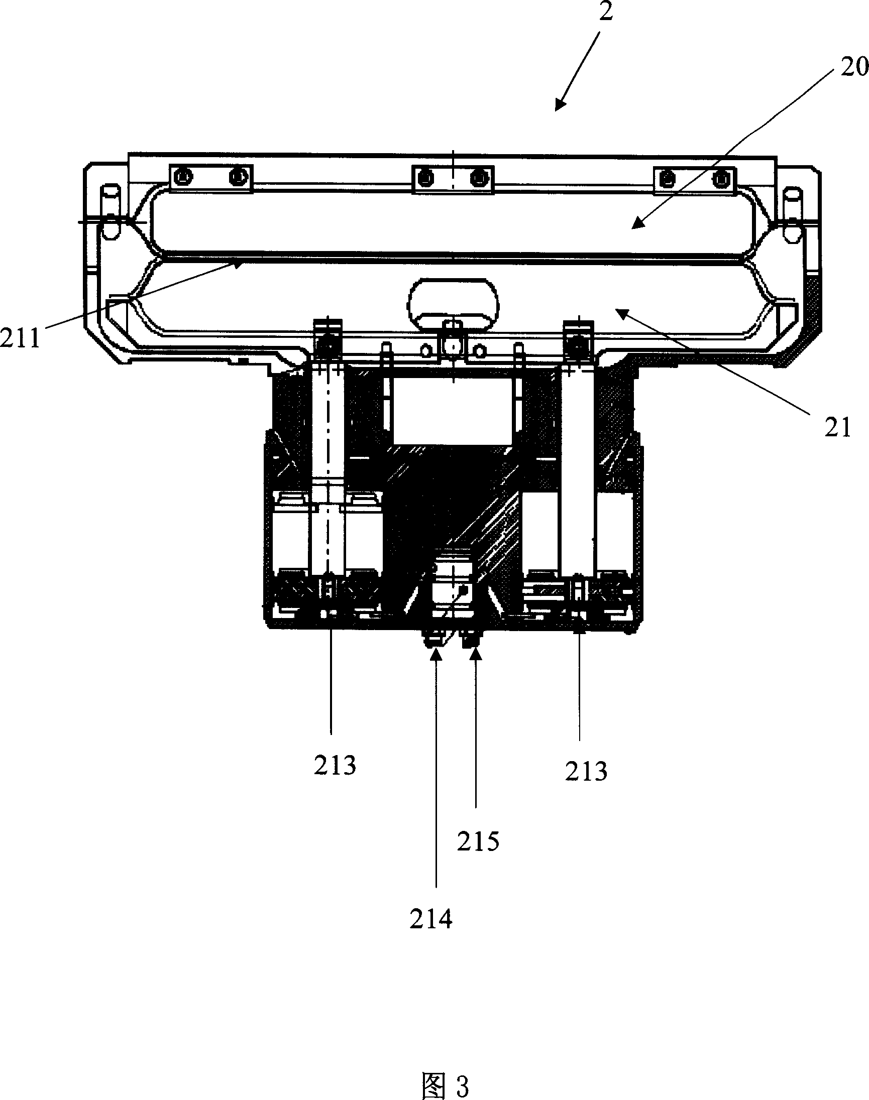
[0059] The method and device for preventing wafer particle defects in a vacuum system according to the present invention will be described in detail below with reference to the accompanying drawings.

[0060] The device for preventing wafer particle defects of the present invention comprises:

[0061] The on-off valve assembly is based on an on-off valve in the prior art, and an on-off valve is added. Therefore, it has a first on-off valve and a second on-off valve. The two valves are set upside down and serve as backup for each other. between bodies. The function of the switch valve is to isolate two different adjacent cavities when the switch valve is in the closed state, so that they can carry out different processes at the same time under different pressures. When the switch valve is in the open state, it provides wafers in and out. The channel of the cavity; the function of the double switch valve is to provide an additional switch immediately when the first switch valve...


PUM


Abstract

The method includes steps: collecting granules; analysis of counted granules; sending information of analyzed result of counted granules to controller of air pressure valve; the controller selects to drive first or second switch valve, and makes switching between two switch valves. The devices in use for the method is composed of switch valve module including first switch valve, and second switch valve, grading analysis instrument, and controller of air pressure valve. Granules generated from switch valve are monitored in real time. One switch valve is working, and the other is standby. Transferring and controlling information of granules makes automatic or manual switching between two valves so as to guarantee continuous operation of machine unit, and yield of wafer.

Description

technical field [0001] The invention relates to a method and a device for preventing wafer defects in semiconductor manufacturing, in particular to a method and a device for a vacuum system to prevent wafer particle defects due to switching valves. Background technique [0002] Vacuum systems are well known for the fabrication of integrated circuits on wafers. The vacuum system includes a central vacuum chamber, the transfer chamber, for going from one process chamber or load chamber to another process chamber. The vacuum system also includes some secondary systems, such as microenvironment, to provide wafers to the load and reaction chambers and collect wafers to send to the next process. The transfer chamber plus the surrounding reaction chamber and assembly area is called cluster equipment. There are switching valve assemblies between two vacuum chambers, such as a transfer chamber and a process reaction chamber. The switch valve assembly includes the switch valve, and...

Claims


Application Information

Patent Timeline
IPC IPC(8): H01L21/00H01L21/67F16K51/02
Inventor 姚政源华宇施敏王铁渠
Owner SEMICON MFG INT (SHANGHAI) CORP
Learn More