Friction revolving barrel of helix freezing apparatus

A technology of freezing device and spiral, which is applied in the direction of household refrigeration device, lighting and heating equipment, cooler, etc., can solve the problems of food hygiene hazards, many metal materials, and difficult cleaning, so as to facilitate mass production, enhance bending resistance, Easy-to-rinse effect

Active Publication Date: 2007-05-16
SIFANG TECH GRP CO LTD
View PDF0 Cites 3 Cited by
  • Summary
  • Abstract
  • Description
  • Claims
  • Application Information

AI Technical Summary

Problems solved by technology

[0002] The frame of the friction drum of the existing spiral freezing device is composed of square tube or rectangular tube straight frame welded on the circular frame. In order to prevent the bypass of the cold air flow, the inside of the frame is also equipped with a metal windshield. The structure not only consumes a lot of metal materials and increases the cost, but also it is not easy to clean the inside of the straight frame tube and the junction of the straight frame and the covered windshield, which brings hidden dangers to the food hygiene of frozen products

Method used


Image

  • Friction revolving barrel of helix freezing apparatus
  • Friction revolving barrel of helix freezing apparatus
  • Friction revolving barrel of helix freezing apparatus

Examples


Embodiment 1

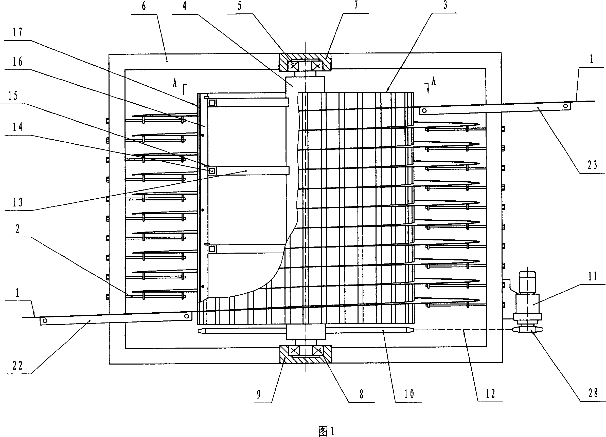
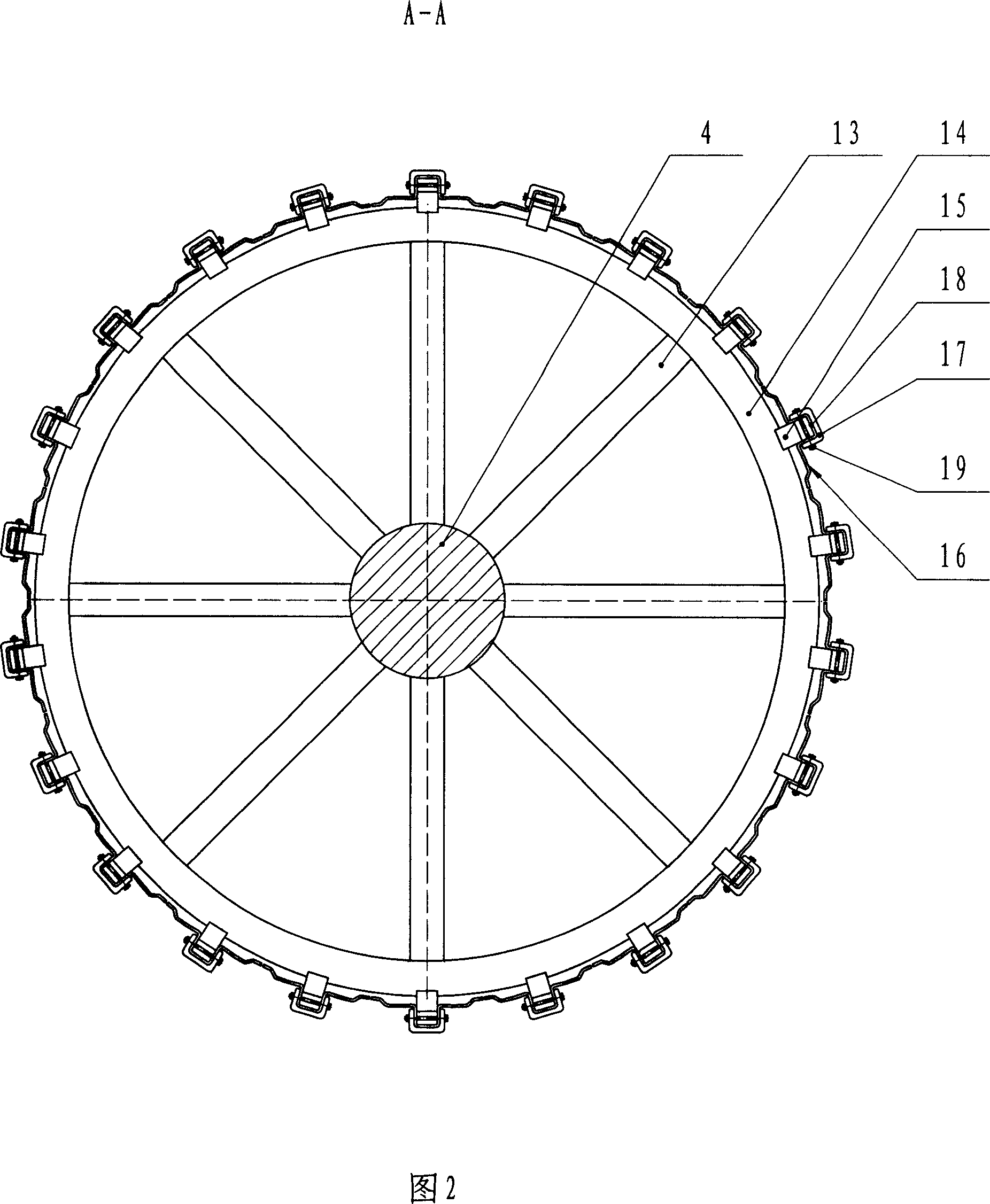
[0023] In the spiral freezing device, the friction drum 3 (see Figure 1) that drives the conveying mesh belt 1 carrying the frozen product to run along the spiral guide rail 2 includes a central shaft 4, and the upper end of the central shaft 4 is placed with a bearing 5 In the upper bearing seat 7 connected with the frame 6, the bearing 8 at the lower end of the central shaft 4 is placed in the lower bearing seat 9 connected with the frame 6, the central shaft 4 is equipped with a sprocket 10, and the sprocket 10 is connected to the The sprocket 28 on the output shaft of the electric reducer 11 on the frame 6 is connected and driven by the electric reducer 11, thereby driving the friction drum 3 to rotate, and the central shaft 4 is fixedly connected with at least two layers of cantilever 13 with radiation distribution , it is four layers in Fig. 1, and the outer end of the cantilever 13 of every layer of radiation distribution is connected with an annular frame 14, and the ou...

Embodiment 2

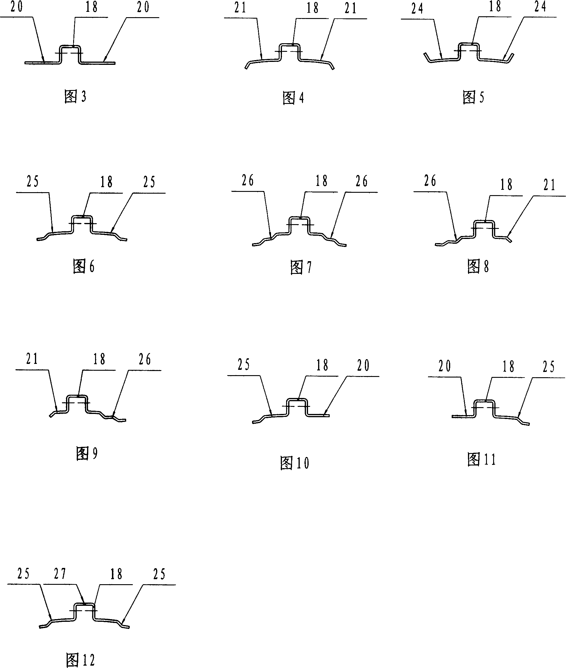
[0025] The difference from Embodiment 1 is that in order to improve the structural stability of the straight frame 16 with wind-shielding sides, the two wind-shielding sides of the straight-bar skeleton 16 with wind-shielding sides are windshields bent inward once respectively. Edge 21 (seeing Fig. 4) or the windshield edge 24 (seeing Fig. 5) that bends once outwards, 18 among Fig. 4, Fig. 5 is boss.

Embodiment 3

[0027] The difference from Embodiment 1 or 2 is that in order to improve the structural stability of the straight frame 16 with the windshield, the two windshield sides of the straight frame 16 with the windshield are respectively bent two times. Wind edge 25 (seeing Fig. 6).


PUM


Abstract

It relates to an abrasion rotating cylinder with spiral freezing device. The central shaft, whose top and bottom ends are set in the frame connected top and bottom bearing base, has a sprocket which connects through chains with the sprocket of the output shaft of the electric decelerator loaded on the frame, it also combines with at least two layers scattered suspension arms with the outside of each layer suspension arm connected with a ring bone structure and the outer circumference of each ring bone structure connecting with a strip bone structure with wind blocking ridge. The boss of the cross section of the strip bone structure taking on the 'n' form is set with abrasion-proof plastic strips of 'n' form profile.

Description

Technical field: [0001] The invention relates to a friction drum of a spiral freezing device. Background technique: [0002] The frame of the friction drum of the existing spiral freezing device is composed of square tube or rectangular tube straight frame welded on the circular frame. In order to prevent the bypass of the cold air flow, the inside of the frame is also equipped with a metal windshield. The structure not only consumes a lot of metal materials and increases the cost, but also the inside of the straight frame tube and the joint between the straight frame and the covered windshield are not easy to clean, which brings hidden dangers to the food hygiene of frozen products. Invention content: [0003] The purpose of the present invention is to provide a technical solution for the friction drum of a spiral freezing device, which is easy to clean, is conducive to the sanitation of frozen products, consumes less material, is beneficial to reduce costs, and has an op...

Claims


Application Information

Patent Timeline
Patent Type & Authority Applications(China)
IPC IPC(8): F25D25/04F25D13/06
Inventor 黄杰梁惠华楼晓华
Owner SIFANG TECH GRP CO LTD
Why Eureka
Try Eureka