Measuring method of remoteness grain based on laser feedback effect

A laser feedback and fine particle technology, which is applied to devices using optical methods, devices using electrical/magnetic methods, measuring devices, etc., can solve problems such as measurement difficulty, and achieve strong repeatability, reliable data, and simple implementation. Effect

Inactive Publication Date: 2007-05-16
UNIV OF SHANGHAI FOR SCI & TECH
View PDF0 Cites 1 Cited by
  • Summary
  • Abstract
  • Description
  • Claims
  • Application Information

AI Technical Summary

Problems solved by technology

It is difficult to measure a small number of tiny particles

Method used


Image

  • Measuring method of remoteness grain based on laser feedback effect
  • Measuring method of remoteness grain based on laser feedback effect
  • Measuring method of remoteness grain based on laser feedback effect

Examples


Embodiment Construction

[0020] The present invention will be further described below in conjunction with the embodiments and the accompanying drawings.

[0021] A method for measuring fine particles based on laser feedback effect: its specific steps are:

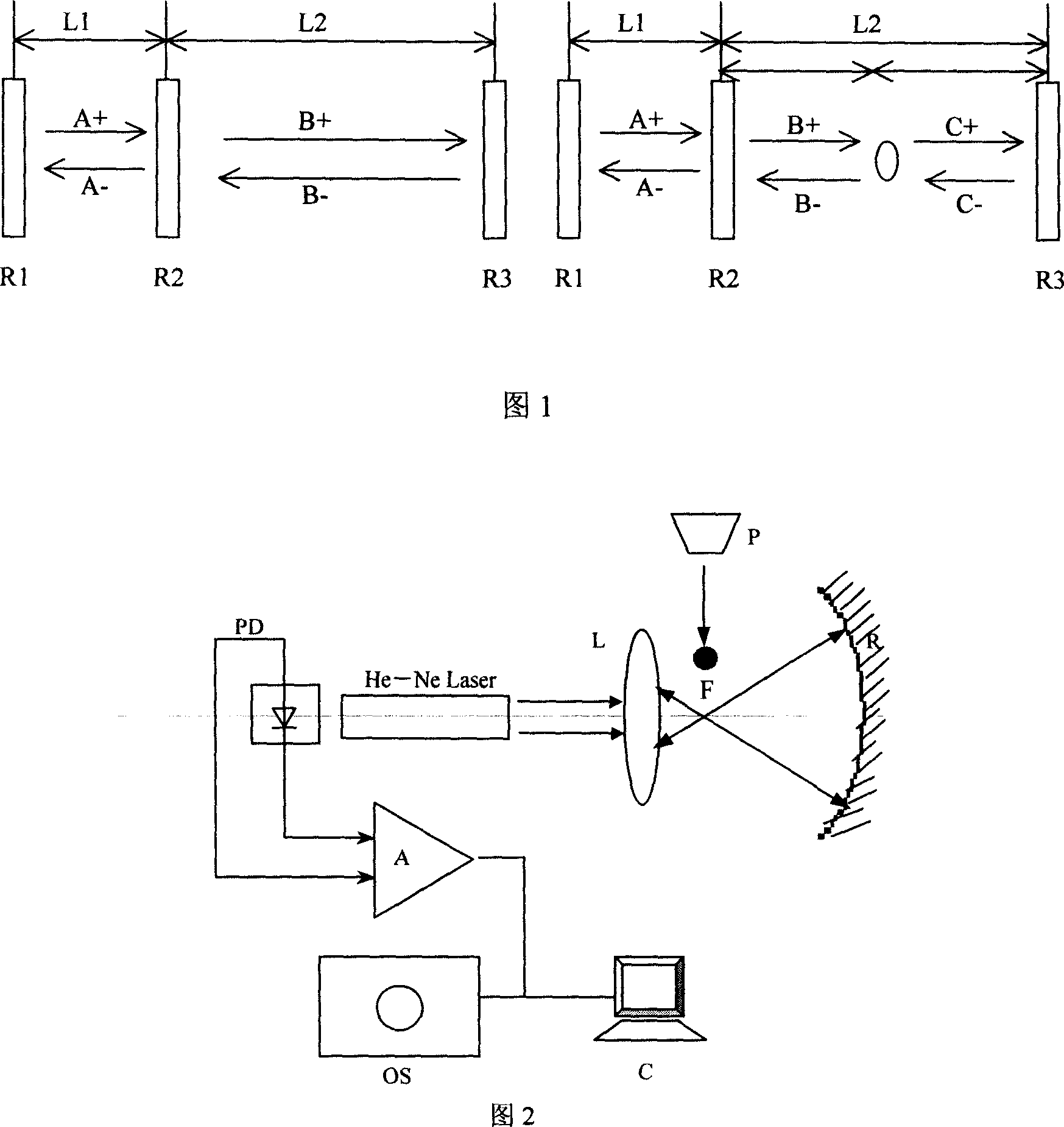
[0022] 1. Build a single particle measurement device based on the laser feedback effect (Fig. 2), select a single-mode helium-neon laser, R in Fig. 2 is a concave total reflection mirror, L is a focus conversion lens, focal length f = 20mm, and the concave total reflection mirror The focal length is 30mm, and F is the confocal focus. The confocal mode of the concave total reflection mirror R and the condenser lens L is adopted to form an additional resonant cavity with the laser resonant cavity. When the outgoing laser is in the additional resonant cavity, in the focal point F area, the appearance of the measured particles is very sensitive, and the scattered light is fed back to the laser, causing a change in the output laser power. PD is a ligh...


PUM


Abstract

This invention discloses one thin particle measurement method based on laser feedback effect, which uses laser added spectrum resonance chamber thin particle diffraction to generate laser feedback effect, wherein, through measuring light energy changes of laser it measures particle size, speed and number parameters; the measurement device adopts heliium neon laser added with concaved total reflection lens and focus co-focus design added resonance chamber relative to difference sizes and speed.

Description

technical field [0001] The invention relates to the field of optical particle measurement, in particular to a measurement device based on the laser feedback effect for measuring parameters such as particle size and moving speed for fine single particles. Background technique [0002] In recent decades, researchers have proposed many light scattering methods and instruments for measuring particle size and concentration, especially in the field of small particle measurement. At present, there are many fine particle measurement techniques and concentration analysis methods. Such as the measurement of small suspended particles in the medical field, the measurement of air pollution in environmental engineering, and the measurement of pollution particles on the surface of silicon wafers in the semiconductor industry. Most of the measuring instruments currently used apply the theory of light scattering, which has certain requirements for the particle concentrati...

Claims


Application Information

Patent Timeline
Patent Type & Authority Applications(China)
IPC IPC(8): G01B11/00G01B11/02G01B7/00G01B7/02G01P3/36G01P3/50G01P3/52
Inventor 孙国强郑继红郑刚
Owner UNIV OF SHANGHAI FOR SCI & TECH
Why Eureka
Try Eureka