Thermal cutting machine and thermal cutting method

A thermal cutting machine, heat technology, applied in welding/cutting auxiliary equipment, welding/welding/cutting items, auxiliary devices, etc., can solve problems such as increased damage degree, and achieve the effect of shortening stop time and simple structure

Inactive Publication Date: 2007-05-23
KOMATSU SANKI
View PDF1 Cites 9 Cited by
  • Summary
  • Abstract
  • Description
  • Claims
  • Application Information

AI Technical Summary

Problems solved by technology

[0003] In addition, since the slats on the workbench are damaged as t

Method used


Image

  • Thermal cutting machine and thermal cutting method
  • Thermal cutting machine and thermal cutting method
  • Thermal cutting machine and thermal cutting method

Examples


Example Embodiment

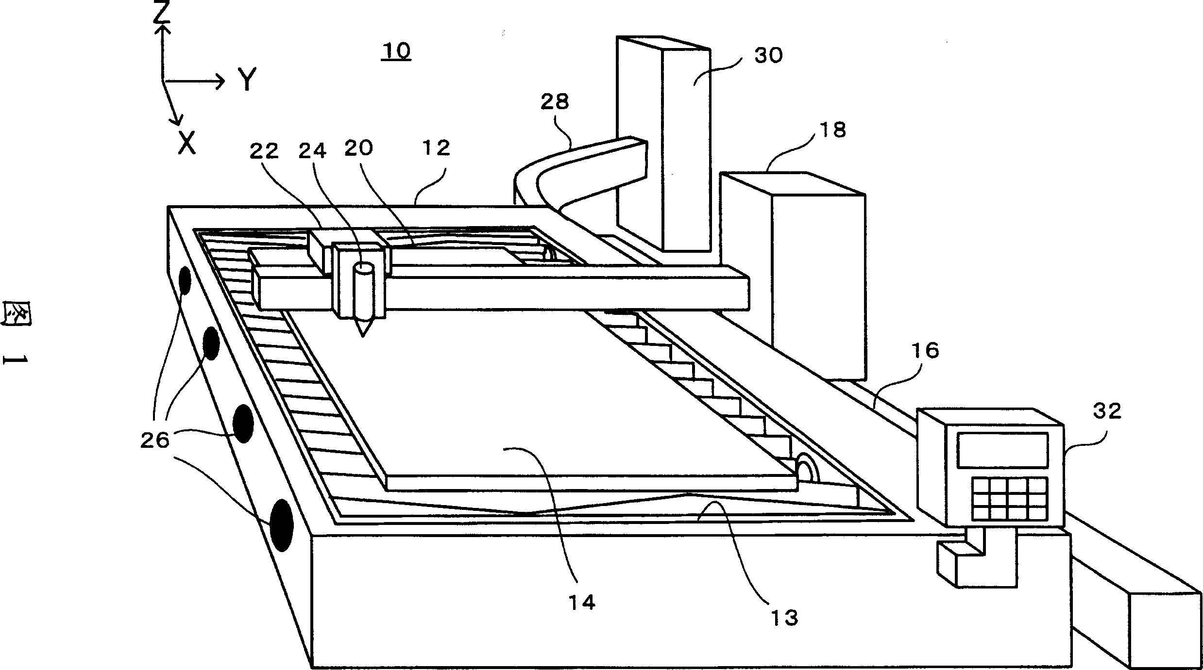
[0037] Fig. 1 is a perspective view of the overall structure of a thermal cutting machine according to the present invention.
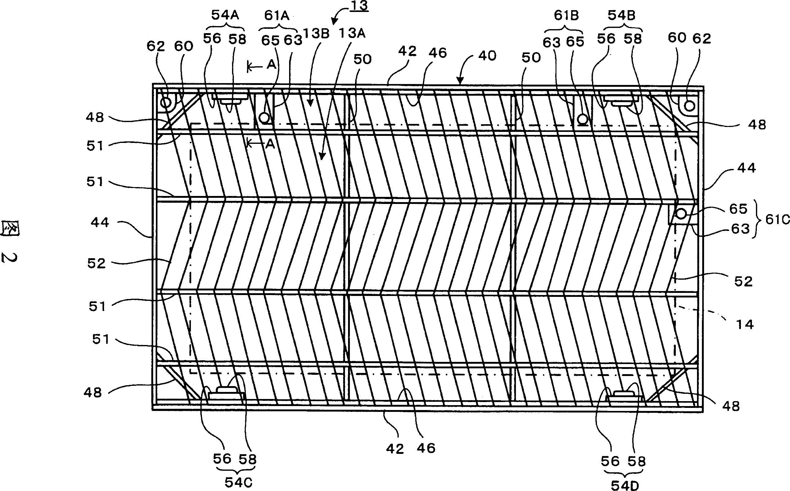
[0038] As shown in Fig. 1, the thermal cutting machine 10 has a box-shaped worktable 12 arranged on a bed. A grid board 13 having a rectangular planar shape is assembled on the upper surface of the workbench 12, and a plate 14 as a material to be cut is placed on the grid board 13. The grid plate 13 is embedded in the opening (refer to the number 79 in FIG. 6) on the upper part of the workbench 12, and can be installed on and removed from the workbench 12. When the board 14 is placed on the grating board 13, the grating board 13 can be lifted from the workbench 12 by a crane and separated from the workbench 12, or unloaded on the workbench 12 by a crane to be assembled on the workbench 12 .

[0039] However, generally, a plate whose plane size is consistent with a specific standard size is widely used as the plate 14. The board 14 having such a standard p...


PUM


Abstract

In thermal cutting machines such as a plasma cutting machine and a laser cutting machine, a stop time involved in loading and unloading of a plate member on a table and replacement of bars is reduced. A grating pallet (13) with a large number of bars for placing a plate member (14) is removably assembled in a table (12). The plate member (14) is placed in advance on the grating pallet (14) in another place, then the grating pallet (13) having the pallet (14) is lifted by a crane, carried to above the table (12), and lowered on the table (12). As soon as cutting is completed, the grating pallet (13) on which a product and residual materials are placed is lifted by the crane to separate it from the table (12) and carried to another place, another grating pallet (13) on which another plate member (14) is placed is carried on to the table (12) by the crane, and cutting of the another plate member (14) is started. The stop time of a thermal cutting machine (10) is only a time to exchange the grating pallets (13).

Description

technical field [0001] The present invention generally relates to thermal cutting machines such as plasma cutting machines, laser cutting machines or gas cutting machines for thermally cutting plates placed on workbenches, and particularly relates to the improvement of the workbench structure to facilitate the transfer of plates and the removal of products . The present invention also relates to a method for cutting boards using a thermal cutting machine. Background technique [0002] Patent Document 1 and the like disclose a table of a heat cutter. A plurality of slats (elongated sheets) are arranged at regular intervals on the upper part of the table of this thermal cutting machine to place the sheets thereon. Usually, the processing steps of the plate are as follows: (1) The operator lifts the plate with a crane, transports it to the workbench, and puts it on the slats. At this time, the thermal cutting machine is in a stopped state. (2) Start the thermal cutting mach...

Claims


Application Information

Patent Timeline
IPC IPC(8): B23K37/04B23K7/10B23K10/00B23K26/10B23K26/38B23K7/00B23K26/14B23K26/16B23K37/00
CPCB23K37/0408B23K7/002B23K2201/18B23K26/38B23K10/00B23K26/0884B23K26/16B23K26/422B23K37/0461B23K26/702B23K2101/18
Inventor 大西知志山口义博
Owner KOMATSU SANKI
Why Eureka
Try Eureka