Film forming apparatus and gasifier
A film-forming device and film-forming technology, applied in gaseous chemical plating, electrical components, semiconductor/solid-state device manufacturing, etc., can solve problems such as futility
- Summary
- Abstract
- Description
- Claims
- Application Information
AI Technical Summary
Problems solved by technology
Method used
Image

Examples
no. 1 example
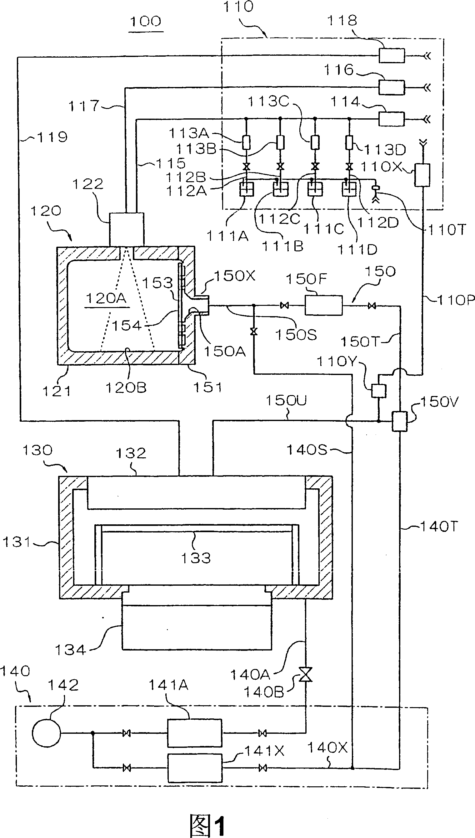
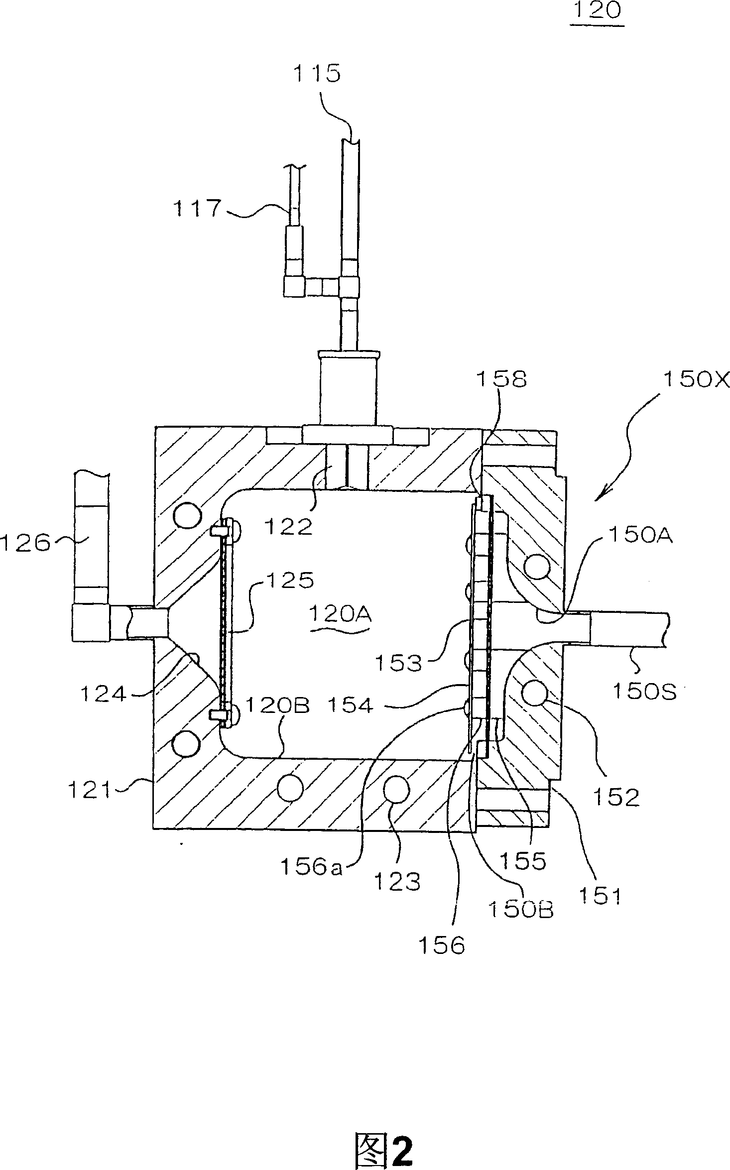
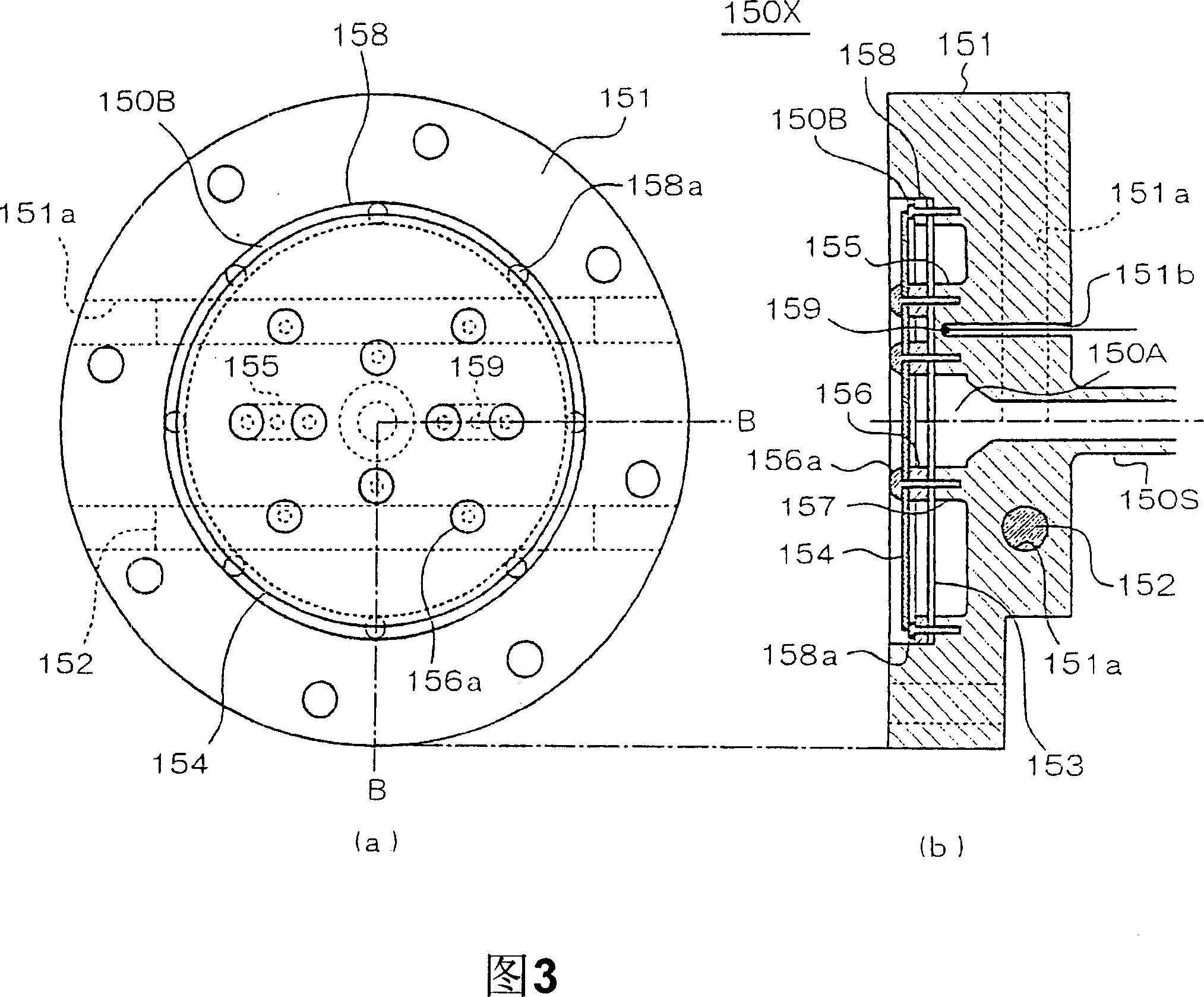
[0103] (First Embodiment) [Detailed structure of raw material gasification section and feed path of raw material gas]
[0104] FIG. 2 is a longitudinal sectional view showing the structure of the above-mentioned raw material vaporization unit 120 in more detail. The raw material vaporization part 120 has heating means 123 such as a heater provided in a partition wall of the vaporization vessel 121 that partitions the raw material vaporization space 120A. The vaporization surface 120B is heated by the heating means 123, and the inside of the raw material vaporization space 120A is also heated by the radiated heat from the vaporization surface 120B. An opening 124 is provided in the vaporization container 121 , and a filter 125 is disposed between the opening 124 and the raw material vaporization space 120A. If a filter is installed elsewhere in the feed path of the raw material gas, the filter 125 may not be used. In addition, the opening 124 is connected to a detection pipe ...
no. 2 example
[0134] [Transportation route of raw material gas]
[0135] In the present embodiment, the raw material gasification unit 120 is arranged above the film forming unit 130 , and the transport path portion composed of the raw material gas transport line 150S and the raw material gas transport line 150T leading out from the raw material gasification unit 120 is configured as much as possible. The bending parts are reduced, and the bending angle of each bending part is reduced. The bending part of the conveying path produces a pressure loss in the pipeline. The larger the bending angle, the greater the pressure loss. This will cause pressure fluctuations in the raw material gas, and the possibility of solidification in the pipeline is high. Therefore, in order to reduce the particles generated in the conveying path As mentioned above, it is effective to reduce the bending portion as much as possible and reduce the bending angle.
[0136] As described above, the line filter 150F ma...
no. 3 approach
[0148] (Third Embodiment) [Structure of Film Formation Section]
[0149] Next, the internal structure of the film formation part 130 of this embodiment is demonstrated with reference to FIGS. 11-13. As shown in FIG. 11 , the film forming part 130 is provided with a gas introduction part 132 on a part of the partition wall (the upper part of the figure) of the film forming container 131 as described above, and the raw material gas and the reaction gas flow from the gas introducing part 132 to the film forming container 131. The inside of the above-mentioned base 133 is introduced. The gas introduction part 132 is provided with a plurality of source gas introduction ports 132a for introducing the above-mentioned source gas inside and a plurality of reaction gas introduction ports 132b for introducing the above-mentioned reaction gas inside, which is a so-called post-mixing type nozzle. Shower structure. In addition, the gas introduction part 132 has a laminated plate structure...
PUM
| Property | Measurement | Unit |
|---|---|---|
| diameter | aaaaa | aaaaa |
Abstract
Description
Claims
Application Information
 - R&D
- Intellectual Property
- Life Sciences
- Materials
- Tech Scout
- Unparalleled Data Quality
- Higher Quality Content
- 60% Fewer Hallucinations
Browse by: Latest US Patents, China's latest patents, Technical Efficacy Thesaurus, Application Domain, Technology Topic, Popular Technical Reports.
© 2025 PatSnap. All rights reserved.Legal|Privacy policy|Modern Slavery Act Transparency Statement|Sitemap|About US| Contact US: help@patsnap.com