Porous light concrete and common concrete composite member, method for producing same, and building therefrom

A technology of composite components and composite structures, which is applied in the direction of building structures, buildings, building components, etc., can solve the problems of inability to meet the needs of building energy conservation, poor heat insulation, thermal insulation effects, and large open-air construction operations, and achieve the benefits of civilization Construction, improve thermal insulation performance, reduce the effect of wet work engineering

Inactive Publication Date: 2007-05-30
郭金鸿
View PDF0 Cites 3 Cited by
  • Summary
  • Abstract
  • Description
  • Claims
  • Application Information

AI Technical Summary

Problems solved by technology

[0003] The purpose of the present invention is to provide a composite member of light-pumped concrete and ordinary concrete, its manufacturing method and a building constructed thereof, to solve the technical problem that the traditional prefabricated building system has poo

Method used


Image

  • Porous light concrete and common concrete composite member, method for producing same, and building therefrom
  • Porous light concrete and common concrete composite member, method for producing same, and building therefrom
  • Porous light concrete and common concrete composite member, method for producing same, and building therefrom

Examples


Embodiment 1

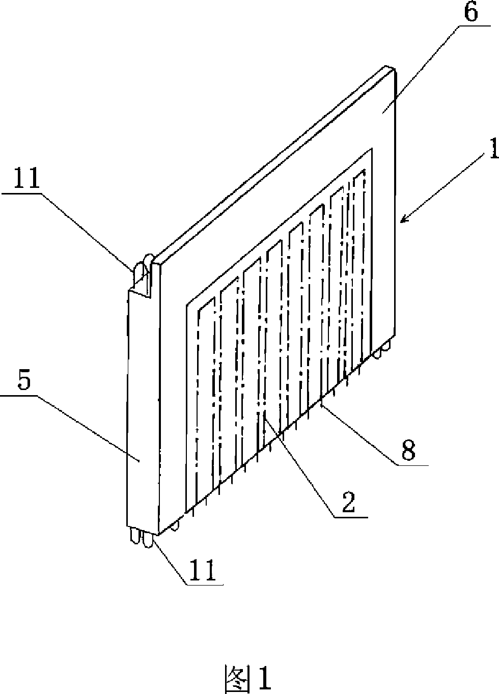
[0056] Embodiment 1 Referring to Fig. 1, a composite member of light-pumped concrete and ordinary concrete is a reinforced concrete two-dimensional plate-shaped member 1 equipped with a steel cage and a steel mesh inside, which is characterized in that: the two-dimensional The load-bearing part of the portal frame and the enclosure and shielding part located in the core of the frame constitute a two-dimensional portal frame light-wall composite structure. The load-bearing part is composed of ordinary reinforced concrete, and the enclosure and shielding part are prefabricated It is composed of a light-weight concrete core board 2 with holes, and the above-mentioned prefabricated light-weight concrete core board 2 with holes is poured into a whole with ordinary reinforced concrete in the load-bearing part of the two-dimensional portal frame;

[0057] The upper part of the two-dimensional portal frame is a semi-finished structural beam 6, and the semi-finished structural beam is o...

Embodiment 2

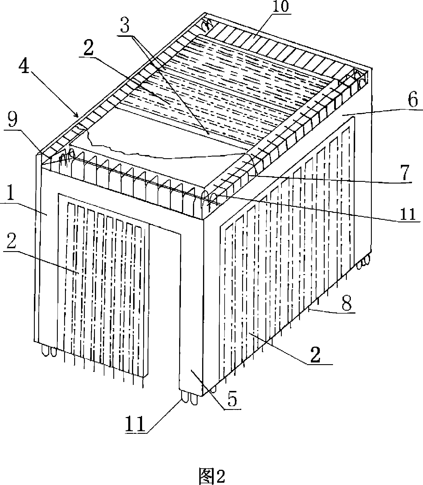
[0060] Embodiment 2 Referring to Fig. 2, another composite member of light-pumped concrete and ordinary concrete is a reinforced concrete box-shaped member 4 equipped with a steel cage and a steel mesh inside, and it is characterized in that: the three-dimensional box-shaped The load-bearing part of the frame and the enclosure and shielding part located in the core of the frame constitute a three-dimensional box-shaped frame light-wall composite structure. Concrete core slab, the above-mentioned prefabricated light-weight concrete core slab and the ordinary reinforced concrete in the load-bearing part of the three-dimensional box-shaped frame are poured into a whole.

[0061] Rib beams 3 are distributed on the upper floor of the above-mentioned three-dimensional box-shaped frame, and prefabricated light-weight concrete core panels with holes are located between the rib beams 3 .

[0062] The upper part of the above-mentioned three-dimensional box-shaped frame is a semi-finishe...


PUM

PropertyMeasurementUnit
Density gradeaaaaaaaaaa

Abstract

The invention relates to a compound member of punching light concrete and common concrete, the manufacturing method and the building with it. The compound structure of 3D box frame light wall comprises bearing part of 3D box frame located at the edge and protecting and shielding part located in the core of frame. The bearing part comprises common reinforced steel concrete and the protecting and shielding part comprises prefabrated core plate of punching light concrete with steel bar net. Said prefabrated core plate of punching light concrete and common steel bar concrete with the bearing part of 3D box frame are cast together. The plate member is light wall compound structure of 2D door frame. Said box member is pentahedron, tetrahedron, or trihedron and one heat insulation layer is compounded on the outer wall. It can satisfy the demand of industrial production and building energy-saving. It is provided with good effect for heat insulation, low construction cost, short working period and little construction work in the open air.

Description

(1) Technical field [0001] The invention relates to a building component, in particular to a composite component, a manufacturing method thereof and a constructed building. (2) Background technology [0002] In order to realize the industrialization of building construction, our country developed the ordinary concrete prefabricated large-slab building system in the early stage, but because of the poor heat insulation and heat preservation effect of the building, the building often has cold bridges and condensation, which does not meet the requirements of building energy conservation. direction of development, and therefore could not continue to develop. In order to solve the problem of heat insulation and heat preservation of buildings, the existing buildings adopt the secondary construction method of first pouring concrete layer by layer, and then pasting the insulation layer. The requirements for concrete pouring equipment are relatively high, and the amount of heat prese...

Claims


Application Information

Patent Timeline
IPC IPC(8): E04C2/38E04B2/56B28B23/02E04B2/82E04B1/348
Inventor 郭金鸿
Owner 郭金鸿
Why Eureka
Try Eureka