Eureka AIR delivers breakthrough ideas for toughest innovation challenges, trusted by R&D personnel around the world.

Testing method and system of safety input output automation based on time

A technology for safe input and test methods, applied in the field of test systems, can solve problems such as imperfect state simplification methods, redundant abstraction time delay transfers, and slow test execution speeds

Inactive Publication Date: 2007-05-30
INST OF SOFTWARE - CHINESE ACAD OF SCI
View PDF0 Cites 8 Cited by
  • Summary
  • Abstract
  • Description
  • Claims
  • Application Information

AI Technical Summary

Problems solved by technology

Although the symbolic state transition diagram generated by this method is the most simple and stable for state reachability analysis, for testing, there are still redundant abstract time delay transitions in the transition diagram generated by this method; in addition, The execution efficiency of this method also needs to be improved
[0005] Due to the limitation of time description ability and the imperfect state simplification method, the implementation system test tools based on timed automata, such as COSPAN, KRONOS, UPPAAL, etc., generally have insufficient tests, slow test execution speed, and are difficult to be used in complex systems. defects such as testing

Method used


Image

  • Testing method and system of safety input output automation based on time
  • Testing method and system of safety input output automation based on time
  • Testing method and system of safety input output automation based on time

Examples


Embodiment 1

[0033] Embodiment 1: Test method based on time input and output automaton model:

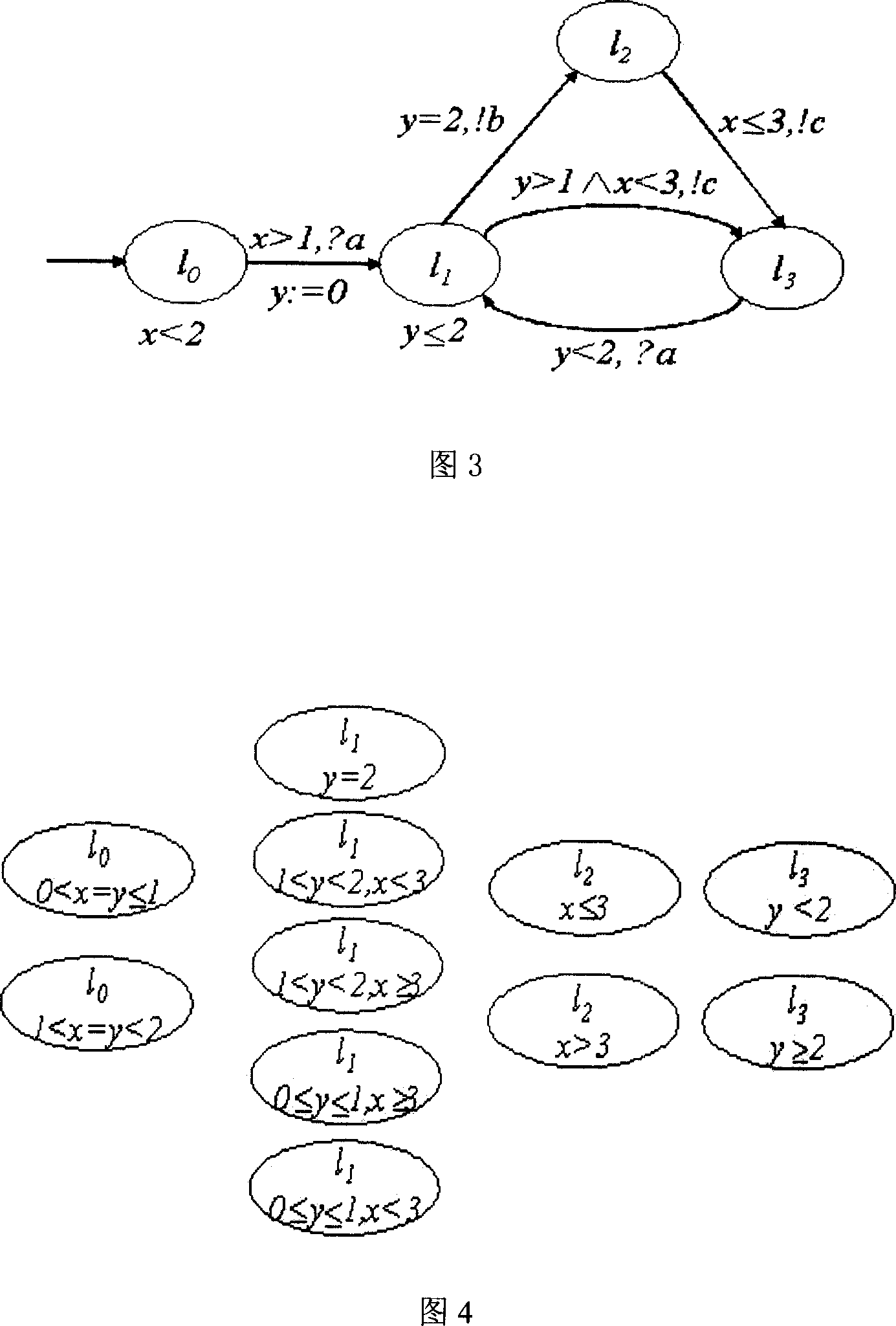
[0034] (1) The formal model of the system under test is established by using the time-safe input-output automaton, the model is shown in Figure 3, and the initial position of the model is I 0 , the clock x and y are both 0, as time changes, when x is greater than 1, the system can accept action a and transfer to position I 1 , reset the clock y to 0 during the transition; similarly, when the system is at I 1 , when the clock x is less than 3 and y is greater than 1, the system can input action c and move to position I 3 superior. Position I in the figure 0 and position I 1 There is a time invariant restriction respectively, which means that the system can be located at I only if x is less than 2 0 , only when y is less than or equal to 2, the system can be located at I 1 .

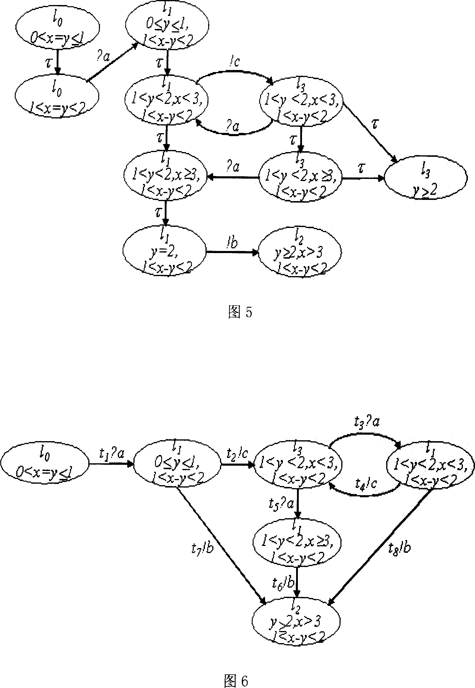
[0035] (2) Simplify the time-input-output automaton model shown in Fig. 3 to obtain the simplest stable symbolic st...

Embodiment 2

[0053] Embodiment 2: Test system based on time input and output automaton model

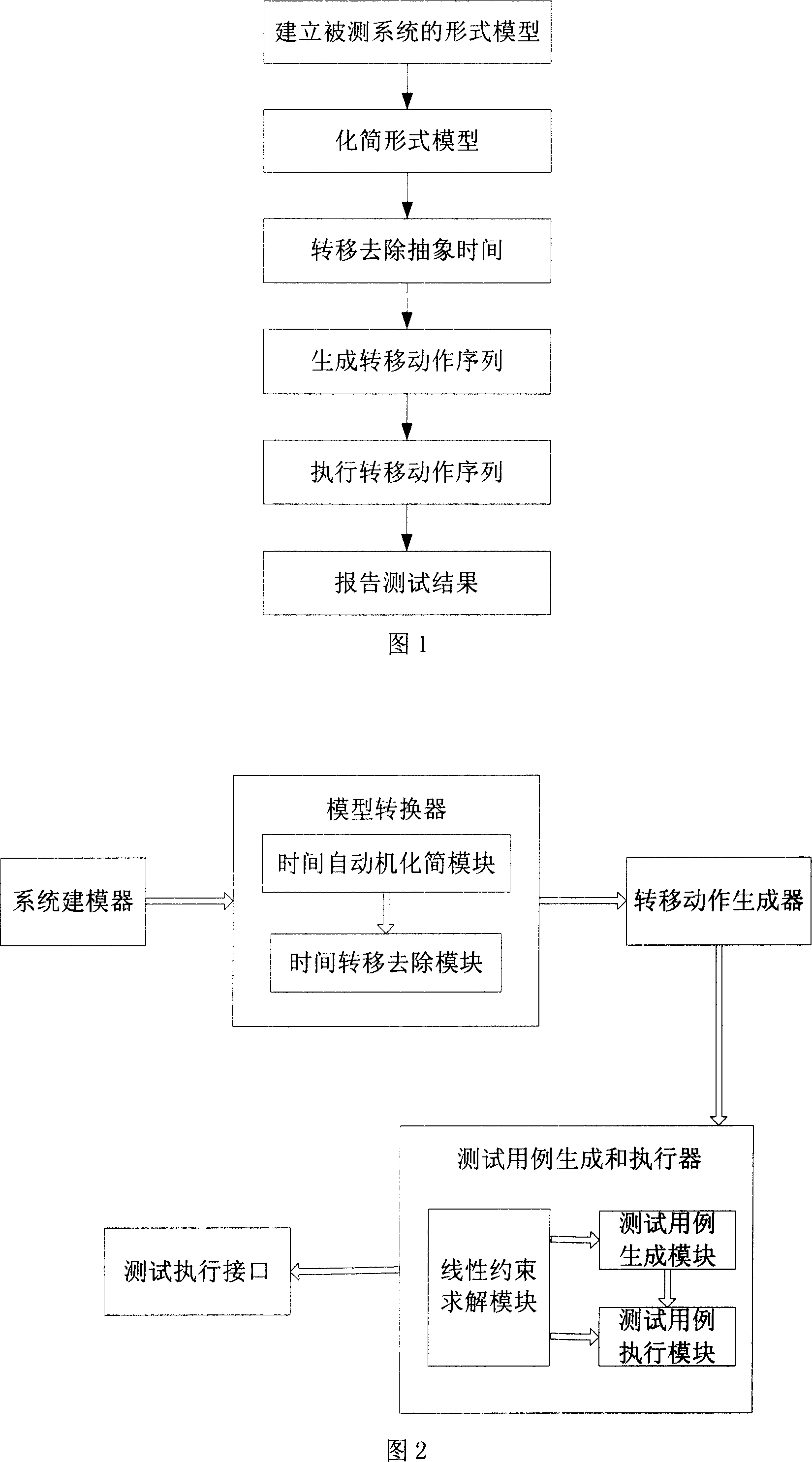
[0054] According to the method described in the first embodiment above, the composition of a software system for implementing the method is shown in Figure 2, the system includes: a system modeler, used to implement step (1) in the first embodiment; Model converter, which includes time automaton reduction module and time transfer removal module, respectively used to realize steps (2) and (3); transfer action generator, used to realize step (4), test case generation and executor , for implementing step (5), which includes a linear constraint solving module, a test case generation module and a test case execution module; a test execution interface, used to realize the test case generation and the connection between the executor and the test manager, All input transfer actions in the test case are sent to the system under test through the test execution interface, and at the same time, the test syst...


PUM


Abstract

The invention presents a real-time testing system and testing method based on the time safe in-out automaton which is a modification of time automaton. The method firstly converts the system model expressed by time safe in-out automaton to stable symbol state transition graph without abstract time delay and lift; the variable transition action sequence which contains time delay and fulfills various structures covering standard is generated statically by the testing method of input / output grade lifting system; at last, the time delay variable is resolved dynamically with introduced time extreme value function and linear constrained-solution method to test. The testing system with the method suits for various black box tests with software system which is restrained by time.

Description

technical field [0001] The invention relates to a test method of a time-safe input and output automaton, and also relates to a test system realized by the test method, which belongs to the technical field of software test. Background technique [0002] A system whose interaction with the operating environment has time constraints is called a real-time system. For many real-time systems, system functional errors or deviations from time constraints can have catastrophic consequences. In order to improve the quality of real-time systems, verification or testing methods are generally used, among which testing is the only method that can verify the dynamic behavior of real-time systems at runtime. Since the 1970s, researchers have proposed many test case generation methods based on various time-independent formal models, such as finite state machines, extended finite state machines, label transfer systems, and some of them, such as: U-method , D-method, W-method and Wp-method h...

Claims


Application Information

Patent Timeline
IPC IPC(8): G06F11/36
Inventor 赵琛陈伟
Owner INST OF SOFTWARE - CHINESE ACAD OF SCI
Why Eureka
Eureka Blog
Learn More