
Engine with two port fuel injectors

A fuel injector and intake port technology, which is applied in the field of engines with two intake port fuel injectors, can solve the problems of reduced fuel economy, increased system cost, assembly of direct fuel injectors, etc.

Inactive Publication Date: 2007-06-06
FORD GLOBAL TECH LLC
View PDF2 Cites 11 Cited by
  • Summary
  • Abstract
  • Description
  • Claims
  • Application Information

AI Technical Summary

Problems solved by technology

First, direct fuel injection may increase system cost
Second, when using a high pressure fuel pump, you may experience reduced fuel economy due to increased parasitic losses
Third, it may be difficult to assemble direct injectors in certain engine configurations, resulting in compromised valve sizes, valve angles, port shapes, injector pointing, or other engine design parameters
However, the inventors herein have recognized that such systems typically provide benefits only within a limited range, such as wide open throttle conditions
Furthermore, this benefit may be diminished by the need to provide acceptable performance under other conditions, such as acceptable combustion at low fuel flow, acceptable cold start operation, and generally acceptable transient fuel response to closed valve injection

Method used


Image

  • Engine with two port fuel injectors
  • Engine with two port fuel injectors
  • Engine with two port fuel injectors

Examples


Embodiment Construction

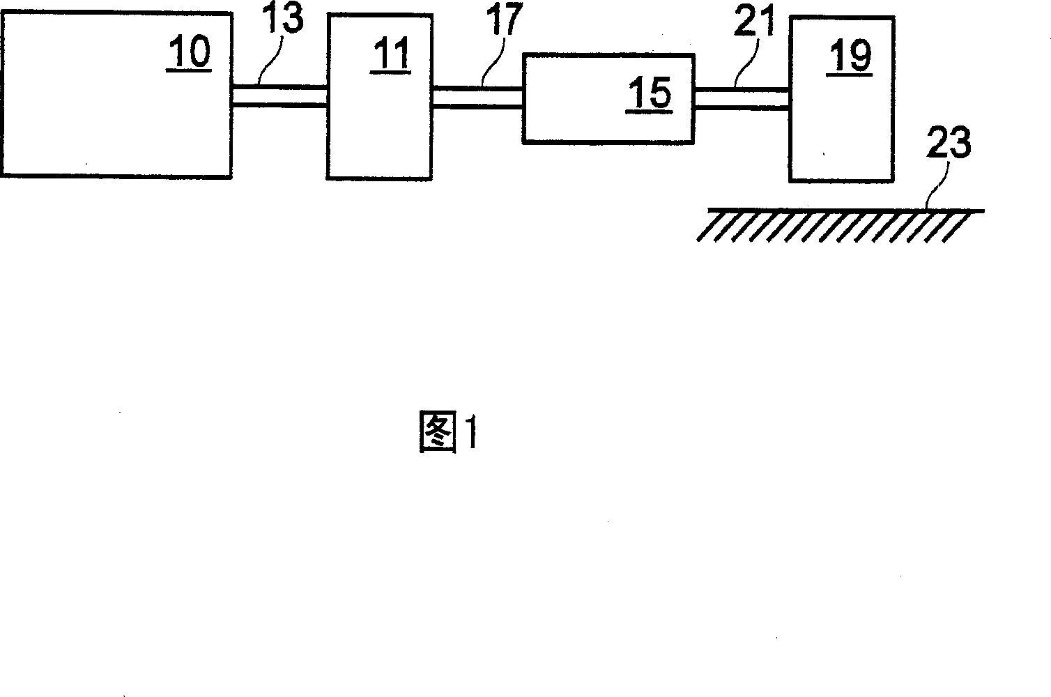
[0042] Referring to FIG. 1 , in this example, an internal combustion engine 10 , described in further detail herein with reference to FIGS. 2 and 3 , is shown coupled to a torque converter 11 via a crankshaft 13 . The torque converter 11 is also connected to a transmission 15 via a turbine shaft 17 . The torque converter 11 has a bypass or lock-up clutch 14 that may be engaged, disengaged, or partially engaged. When the clutch is disengaged or partially engaged, the torque converter is in the unlocked state as described. The lock-up clutch 14 may be, for example, electrically actuated, hydraulically actuated, or electrohydraulically actuated. The lock-up clutch 14 receives a control signal (not shown) from a controller, as described in more detail below. The control signal may be a pulse width modulated signal for engaging, partially engaging, and disengaging the clutch based on engine, vehicle, and / or transmission operating conditions. The turbine shaft 17 is also referred...


PUM


Abstract

The invention provides a system for an engine, comprising of a cylinder located in the engine, a first port injector for injecting a first fuel into the cylinder, and a second injector outside the cylinder for injecting a second fuel into the cylinder. In this manner, the improved air inlet cooling operation can be realized so as to increase compression and / or increase pressure while reduce the engine knock limit, and the weakness of the direct injection system can be also avoided. In addition, by employing a plurality of injectors, one of the injector can be designed to inject when the valveis open while the other injector can be designed to inject when the valve is close, so that the air inlet cooling can be improved.

Description

technical field [0001] The present invention relates to systems and methods for injecting fuel into engine cylinders. Background technique [0002] Engines may use various forms of fuel delivery to provide the required amount of fuel for combustion in each cylinder. One type of fueling uses a single centrally located injector to provide fuel to one or more cylinders. Another type of fueling uses port injectors for each cylinder to deliver fuel to the corresponding cylinder. Yet another type of fueling uses direct injectors for each cylinder. [0003] Additionally, engines have been described that use more than one injector to provide fuel to a single cylinder in an attempt to improve engine performance. In particular, an engine using port fuel injectors and direct injectors in each cylinder of the engine is described in US 2005 / 0155578. [0004] Another approach utilizing multiple injection locations for different fuel types is described in Heywood et al., entitled "Calc...

Claims


Application Information

Patent Timeline
Patent Type & Authority Applications(China)
IPC IPC(8): F02D19/06F02D19/08F02D35/00F02D41/00
CPCF02B2275/16F02D41/3029F02M25/0715Y02T10/123F02M25/089F02D19/061F02M25/0228Y02T10/36F02M37/0064F02B23/105F02D19/0692F02B2075/125F02D41/0025F02D41/3094F02B31/06F02D13/0219F02D19/088F02D19/081F02M25/0752F02D19/084F02M25/0227F02M26/01F02M26/13Y02T10/12Y02T10/30
Inventor 汤姆·G·利昂鲍勃·艾伯特·斯坦杰夫·切斯特·莱杰克
Owner FORD GLOBAL TECH LLC
Learn More