Precision current sensor used for electric machine control

A current sensor, motor control technology, applied in the direction of DC motor speed/torque control, excitation or armature current control, control system, etc. problems, to achieve the effect of maintaining output accuracy, accurate current detection, and accurate current measurement

Inactive Publication Date: 2007-06-06
陆启建 +1
View PDF0 Cites 2 Cited by
  • Summary
  • Abstract
  • Description
  • Claims
  • Application Information

AI Technical Summary

Problems solved by technology

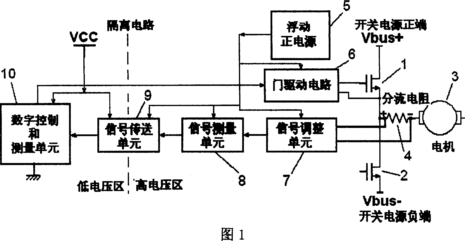
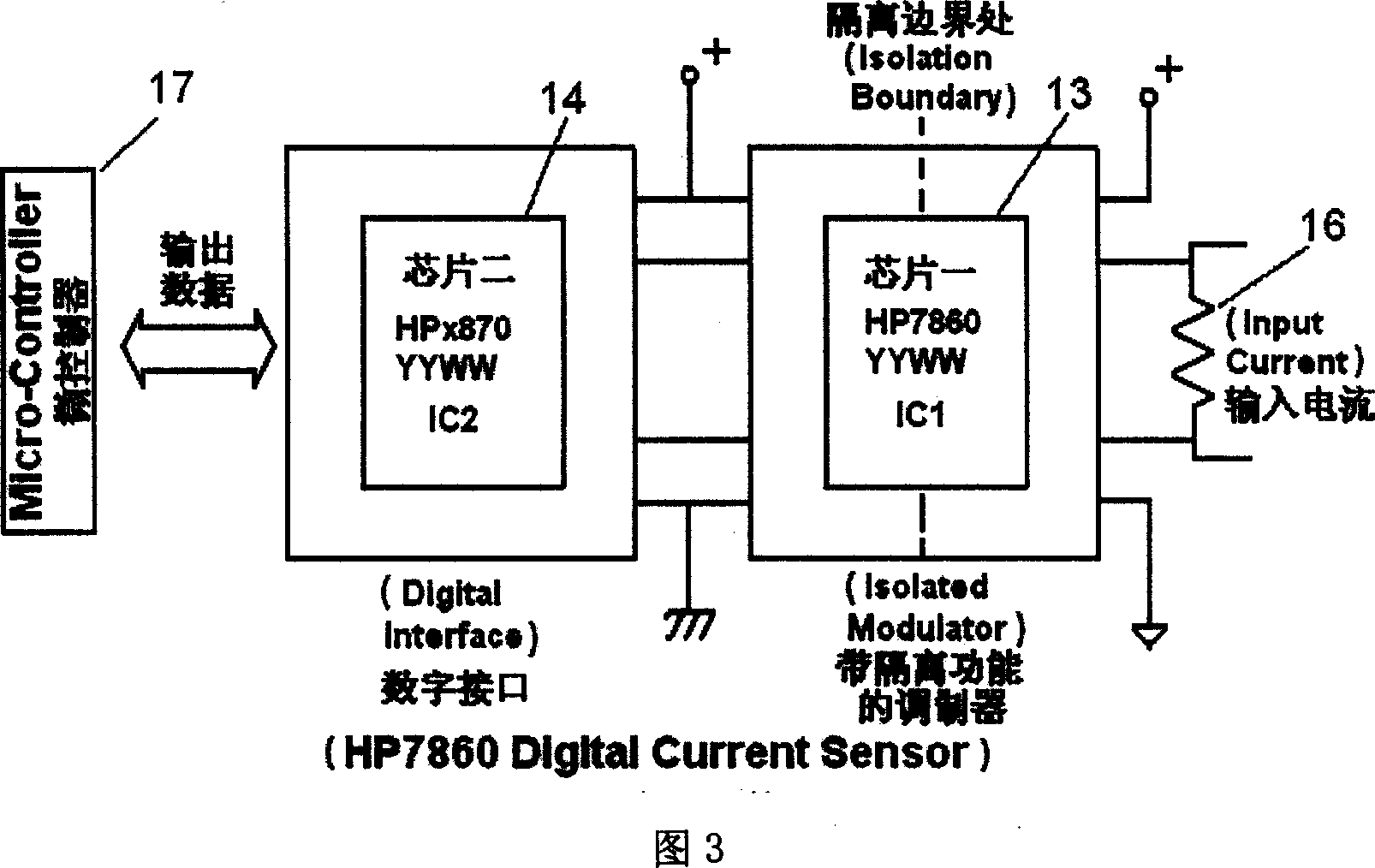
Since each shunt resistor channel requires one such chip 14, the overall cost is increased and the complexity is increased in multi-phase motor control
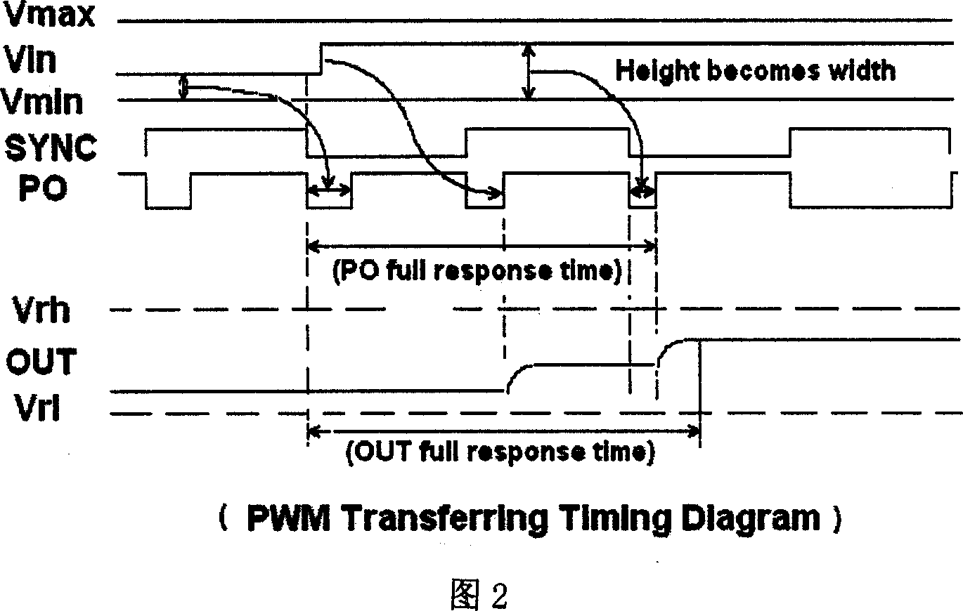
[0017] Another disadvantage of the HP7860 is that the resolution decreases as the data transmission rate increases. For example, if 12-bit precision data is to be transmitted, the transmission delay is 18uS, and when 14-bit precision is required, the delay reaches 94uS, which is much higher than the general switching period of 50us=1 / 20Khz

Method used


Image

  • Precision current sensor used for electric machine control
  • Precision current sensor used for electric machine control
  • Precision current sensor used for electric machine control

Examples


Embodiment Construction

[0052] The present invention will be illustrated further in the following description, and the parts in the figure will be represented by their numbers throughout the text.

[0053] Made according to the characteristics of the present invention, Fig. 4 is a new precise current sensor system, this circuit system includes shunt resistor 4, a signal adjustment unit 19, a signal transmission unit 20, and a level shift unit 21. The original signal measuring unit 8 in Fig. 1 is omitted in this design, thereby simplifying the circuit, reducing the cost, and greatly eliminating the signal delay caused by this component.

[0054] FIG. 5 is an implementation of the signal conditioning unit 19 in the new sensor system (FIG. 4), which features a differential amplifier 24 to linearly amplify the current signal from the shunt resistor.

[0055] Another feature of the present invention is that only resistors are used as feedback and input elements in the amplifier 24, and the input resistors...


PUM


Abstract

A current transducer used for controlling motor consists of a signal regulation unit including a differential amplifier and a voltage reference unit; a signal transmission unit including a pair of double clamping diodes, a DC power supply VCC, a set of capacity and a pair of resistances; a level shift circuit including a differential amplifier with its feedback resistance being at the same value as its input resistance.

Description

1. Technical field [0001] The invention relates to a sensor device for simplifying the motor control circuit and improving the working frequency of the motor control switch. More specifically, the present invention relates to improving the signal-to-noise ratio of the current sensor before analog-to-digital conversion (referred to as AD conversion), so that the detection accuracy is not affected by the switching frequency. The switching frequency can be increased from the current 20KHz to several times. 2. Background technology [0002] In terms of the performance of the motor control system, it is always inseparable from a subject, that is, how to obtain the phase current information of the motor accurately and in time. Unfortunately, these phase current signals are always generated by high voltage switching power supplies. This supply voltage is too high for the digital control unit to process these signals directly without damaging the circuit. Therefore, some special ...

Claims


Application Information

Patent Timeline
IPC IPC(8): H02P7/06H02P7/24H02P7/28H02P7/285H02P7/29G01R19/25G01R19/252
Inventor 陆启建陆启湘
Owner 陆启建
Why Eureka
Try Eureka