
Plane-cabin energy-collected cutting apparatus

A cutting device and aircraft cabin technology, applied in the field of explosive cutting, to achieve the effect of convenient use, simple assembly and strong cutting ability

Inactive Publication Date: 2007-06-13
XIAN MODERN CHEM RES INST
View PDF1 Cites 15 Cited by
  • Summary
  • Abstract
  • Description
  • Claims
  • Application Information

AI Technical Summary

Problems solved by technology

After investigation and new search of relevant materials at home and abroad, no relevant reports were found on the use of energy-concentrating cutting devices to explosively cut and open windows for aircraft cabins

Method used


Image

  • Plane-cabin energy-collected cutting apparatus
  • Plane-cabin energy-collected cutting apparatus

Examples


Embodiment Construction

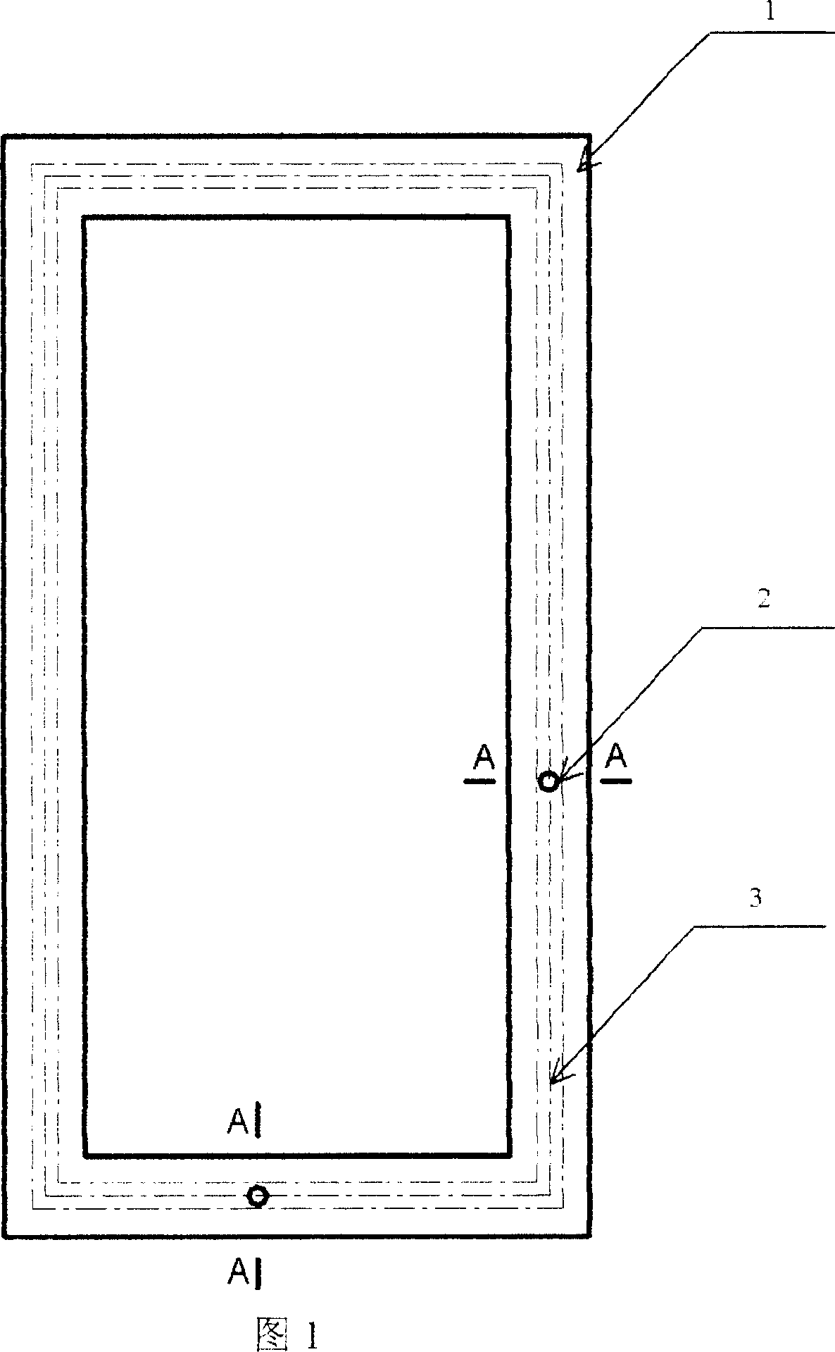
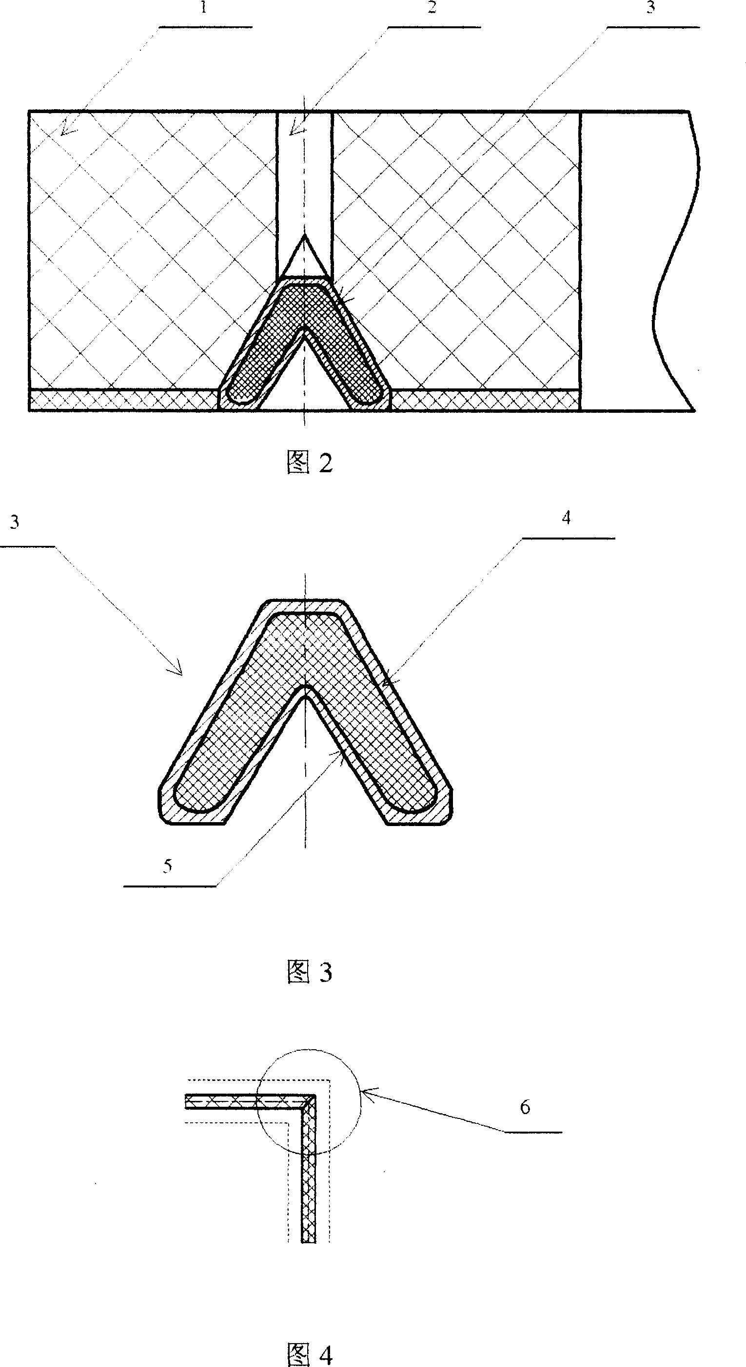
[0017] 1. The present invention is implemented with reference to Figures 1, 2, 3, and 4

[0018] 1.1 Preparation of shaped cutting cord

[0019] First, according to the model and structure of the shaped cutting cord 3, design and manufacture different models of molds; then put the mold into the hydraulic drawing machine, and load the explosive into the shell 4 of the shaped cutting cord 3 according to the technological requirements. 4 is a lead-antimony alloy tube containing 1% antimony; then put the metal tube filled with explosives into a "rolling drawing machine" and repeatedly rolling and drawing until the taper of the drug-shaped cover 4 meets the requirements of energy-converging cutting Cable 3.

[0020] 1.2 Preparation of protective cover

[0021] First, select the polyethylene foam sheet of the specified thickness and standard specifications, and cut the rectangular protective cover 1 outline blank with a high-speed band saw according to the size requirements of the drawi...


PUM


Abstract

This invention discloses a cumulative cut device for airplane compartments, which fills explosive charges in angles at the corners of the device to transfer the explosion continuously, applies a metal explosive cover not generating pestles to increase the cut depth of non-uniform compound materials when cutting on planes in linearity and applies lags capable of absorbing shock waves and scattered materials to increase the safety.

Description

Technical field [0001] The invention is an energy-concentrating cutting device for aircraft cabins, which belongs to the field of explosive cutting and is mainly used for cutting non-homogeneous materials such as aircraft cabins. Background technique [0002] With the development of the anti-terrorism struggle, in accordance with the needs of anti-hijacking operations, the anti-terrorism force has proposed a convenient, rapid and safe method to cut the aircraft cabin. At present, there are three main cutting methods for metal plates and pipes including cylinders at home and abroad: mechanical cutting, chemical cutting and explosive cutting. Among them, mechanical cutting and chemical cutting require huge equipment and slow cutting speed, which is not suitable for rapid cutting under special circumstances. Explosive cutting uses linear shaped charge. When the explosive explodes, the charge type cover is crushed to form a high-speed continuous Jet cutting metal materials. Just like...

Claims


Application Information

Patent Timeline
IPC IPC(8): B26F1/26F42D3/00
Inventor 景振禹邢春洪王宝兴宁建会张双计李森元陈龙孙博祥樊春阳吴廷汉鱼溶韦国平孔军利雷卫国曹红砚
Owner XIAN MODERN CHEM RES INST
Learn More