Control circuit and control method for DC-DC converter

A control circuit, DC-DC technology, applied in the field of subharmonic oscillation, which can solve problems such as switching frequency fluctuations

Active Publication Date: 2007-06-13
CYPRESS SEMICON CORP
View PDF2 Cites 3 Cited by
  • Summary
  • Abstract
  • Description
  • Claims
  • Application Information

AI Technical Summary

Problems solved by technology

Therefore, the switching frequency of transistor FET1 fluctuates with the input voltage Vin.

Method used


Image

  • Control circuit and control method for DC-DC converter
  • Control circuit and control method for DC-DC converter
  • Control circuit and control method for DC-DC converter

Examples


Embodiment Construction

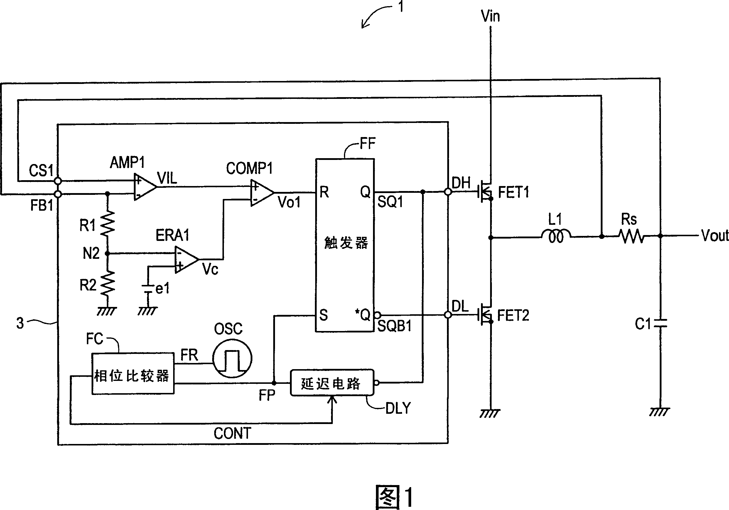
[0026] A DC-DC converter 1 according to a first embodiment of the present invention will now be explained with reference to FIG. 1 . The DC-DC converter 1 includes a control section 3, a choke coil L1, a main switching transistor FET1, a synchronous rectification transistor FET2, a smoothing capacitor C1, and a current detection resistor Rs.

[0027] In FIG. 1, the input voltage Vin is connected to the input terminal of the transistor FET1, and the input terminal of the choke coil L1 is connected to the output terminal of the transistor FET1. The output voltage Vout is output from the output terminal of the choke coil L1. The output terminal DH of the control part 3 is connected to the control terminal of the transistor FET1. The input terminal of the transistor FET2 as a synchronous rectification switching circuit is grounded, and its output terminal is connected to the input terminal of the choke coil L1. The output terminal DL of the control part 3 is connected to the con...


PUM


Abstract

The object of the present invention to provide a control circuit and a control method for a current mode control type DC-DC converter capable of preventing a subharmonic oscillation even if an on-duty is not less than 50% and capable of preventing a switching frequency from fluctuating depending on an input voltage. When a high-level output signal Vo 1 is inputted to a reset input terminal R of a flip-flop FF, a transistor FET 1 is turned off. A phase comparator FC outputs a comparison result signal CONT in accordance with a phase difference between a delay signal FP and a reference signal FR. A delay circuit DLY outputs a high-level delay signal FP after the passage of a delay time DT adjusted in accordance with the comparison result signal CONT from the turn-off of the transistor FET 1 . The transistor FET 1 is turned on in accordance with an input of the high-level delay signal FP.

Description

technical field [0001] The present invention relates to a control circuit and a control method for a current mode control type DC-DC converter, and more particularly, the present invention relates to preventing subharmonic oscillations that occur when the duty cycle exceeds 50%. Background technique [0002] FIG. 9 is a circuit diagram of a constant off-time controlled current mode DC-DC converter 100 . When the main switching transistor FET1 is turned on, the inductor current flowing through the choke coil L1 increases. When the inductor current fed back via the input terminal FB1 becomes larger than the error amplification signal Vc, the transistor FET1 is only turned off for a fixed time. After this fixed off-time, the transistor FET1 is turned on again. [0003] Furthermore, Japanese Unexamined Patent Publication No. 2002-223562 and No. 2005-143197 are disclosed as related art. Contents of the invention [0004] In the DC-DC converter 100, although the turn-off time...

Claims


Application Information

Patent Timeline
Patent Type & Authority Applications(China)
IPC IPC(8): H02M3/155
CPCY02B70/1466H02M3/1588Y02B70/10H02M3/155
Inventor 长谷川守仁
Owner CYPRESS SEMICON CORP
Why Eureka
Try Eureka