Heat exchange device

A technology of heat exchangers and heat, applied in heating methods, household heating, indirect heat exchangers, etc., can solve the problems of reducing heat transfer and enhancing

Inactive Publication Date: 2007-06-20
OXYCELL HLDG
View PDF1 Cites 4 Cited by
  • Summary
  • Abstract
  • Description
  • Claims
  • Application Information

AI Technical Summary

Problems solved by technology

However, the presence of such a layer results in enhanced thermal isolation of the secondary surface from the working airflow, thereby reducing heat transfer

Method used


Image

  • Heat exchange device
  • Heat exchange device
  • Heat exchange device

Examples


Embodiment Construction

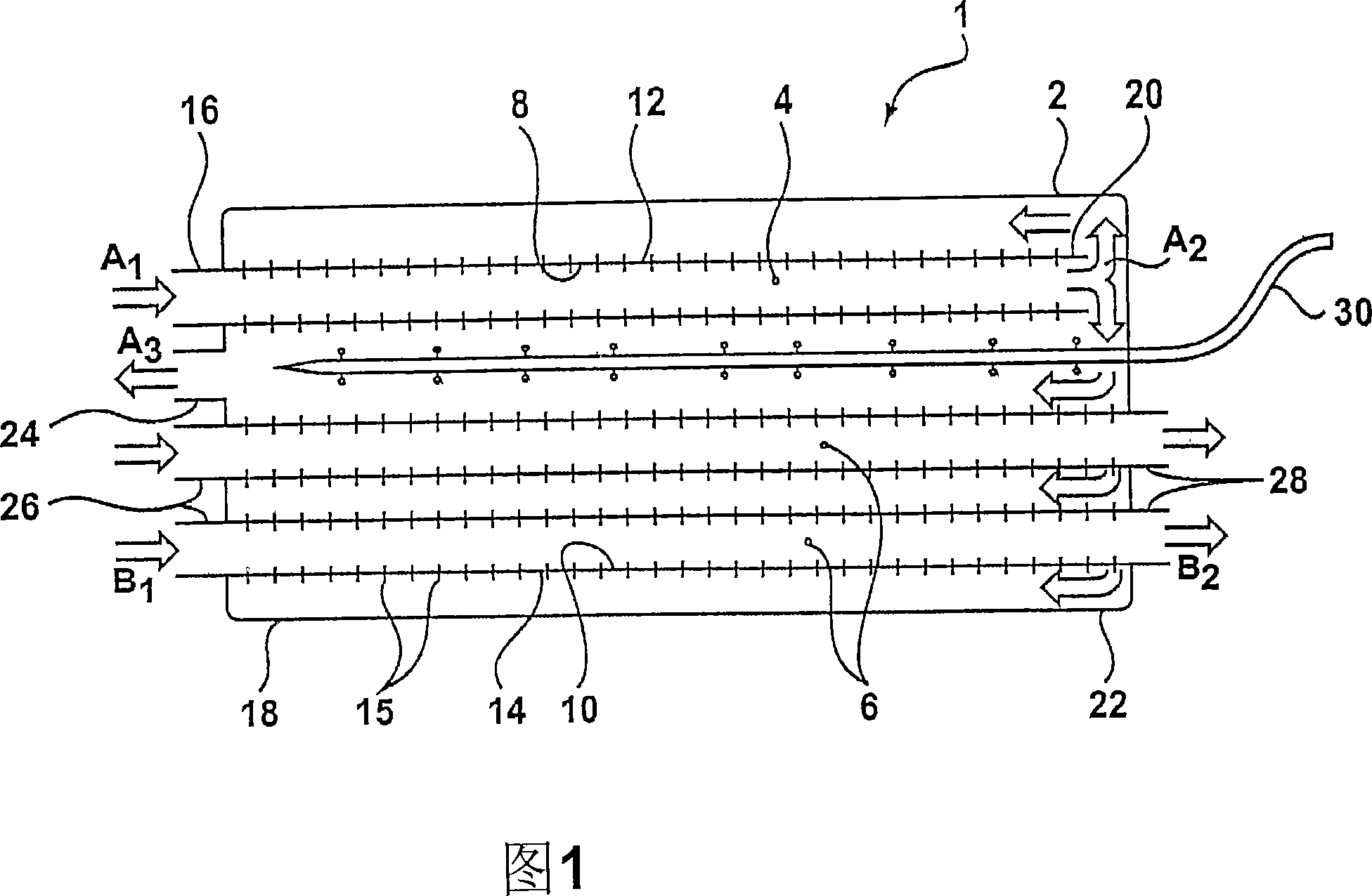
[0033] Fig. 1 shows a schematic diagram of an evaporative heat exchanger 1 according to the invention. The heat exchanger 1 comprises a generally elongated housing 2 in which working channels 4 extend. A plurality of product channels 6 also pass through the housing 2, the product channels 6 and the working channel 4 being generally parallel and spaced apart from each other. The working channel 4 and the product channel 6 respectively have a main surface 8, 10 arranged inside the channel, and a secondary surface 12, 14 arranged outside the channel. The working channel 4 and the product channel 6 are provided with a plurality of heat conducting elements 15 in the form of cooling fins.

[0034] The working channel 4 has an inlet 16 disposed externally of the housing 2 adjacent a first end 18 . An outlet 20 of the working channel 4 is provided in the housing 2 adjacent to the second end 22 . The housing 2 is also provided with a discharge opening 24 adjacent the first end 18 . ...


PUM


Abstract

An evaporative heat exchanger comprises a working channel comprising primary and secondary surfaces and a plurality of product channels comprising primary and secondary surfaces. A liquid supply provides an evaporative liquid to t he secondary surfaces. A product fluid may circulate through the product channels in heat exchanging contact with the primary surfaces thereof. The primary surface of the working channel is in flow communication with the secondary surfaces of both the working channel and the product channels such that a working fluid may flow first o ver a primary surface of the working channel and subsequently over the secondary surfaces where it absorbs liquid by evaporation.

Description

technical field [0001] The present invention relates to heat exchange devices, and more particularly to evaporative heat exchangers. The invention also relates to a device operative to provide heat recovery in combination with ventilation. Background technique [0002] An evaporative cooler is a device that uses the latent heat of evaporation of a liquid to provide cooling. The principle of evaporative cooling has been known for many centuries. For example, covering an object with a damp cloth may keep the object cool through the evaporation of fluid from the cloth. By continuously adding moisture to the cloth, the cooling effect can be maintained indefinitely without inputting electrical power. By evaporating moisture into the air stream in this way, the lowest temperature can be reached, forming the wet bulb temperature of the air. An indirect evaporative cooler utilizes this principle. The product air flow over the primary surface of the heat exchange element is cool...

Claims


Application Information

Patent Timeline
Patent Type & Authority Applications(China)
IPC IPC(8): F24F5/00F28C3/08F24F1/0073F28D5/02
CPCY02B30/545F24F2001/0092F28D5/02F24F5/0035F24F1/0007Y02B30/54F24F1/0073F24F5/00F28C3/08
Inventor J·A·M·赖因德斯A·J·L·奈森
Owner OXYCELL HLDG
Why Eureka
Try Eureka